This article discusses sequential systems using the Omron PLC logic based on the washing machine automation example.
Washing Machine Automation
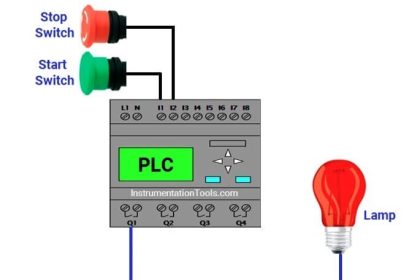
This PLC program uses 2 buttons, the START_WASH (0.00) button is used to Turn ON the system and the STOP_WASH (0.01) button is used to Turn OFF the system.
When the START_WASH (0.00) button is pressed, the Output WATER_IN (100.00) will be ON for 15 seconds to carry out the water filling process.
After the Output WATER_IN (100.00) is OFF, the Mixing process will be carried out. The MIX_FORWARD (100.01) and MIX_REVERSE (100.02) Outputs will be ON (alternately) 4 times with a time interval of 5 seconds.
When the Mixing process is complete, the Output DRYER (100.03) will be ON for 20 seconds to carry out the drying process.
The Output ALARM (100.04) will be ON after the drying process is complete. The Output ALARM (100.04) will be OFF if the STOP_WASH (0.01) button is Pressed.
IO List
| Comment | Input (I) | Output (Q) | Memory Bits | Memory Word | Timers |
| START_WASH | 0.00 | ||||
| STOP_WASH | 0.01 | ||||
| WATER_IN | 100.00 | ||||
| MIX_FORWARD | 100.01 | ||||
| MIX_REVERSE | 100.02 | ||||
| DRYER | 100.03 | ||||
| ALARM | 100.04 | ||||
| TIMER_1 | T0000 | ||||
| TIMER_2 | T0001 | ||||
| TIMER_3 | T0002 | ||||
| TIMER_4 | T0003 | ||||
| SYSTEM_ON | W0.00 | ||||
| PV_FORWARD_REVERSE | D0 |
Omron PLC Logic
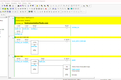
RUNG 0 (START_WASH)
In this Rung, when the START_WASH (0.00) button is pressed, the memory bit SYSTEM_ON (W0.00) changes to ON state. Because it uses latching, the memory bit SYSTEM_ON (W0.00) remains ON even though the START_WASH (0.00) button has been Released.
The memory bit SYSTEM_ON (W0.00) will be OFF if the STOP_WASH (0.01) button is Pressed.
RUNG 1 (WATER IN)
When NO contact of the memory bit SYSTEM_ON (W0.00) in the HIGH state, the Output WATER_IN (100.00) will be ON and the TIMER_1 (T0000) Timer Starts counting up to 15 seconds.
The Output WATER_IN (100.00) will be OFF when NC contact of Timer TIMER_1 (T0000) in the HIGH state.
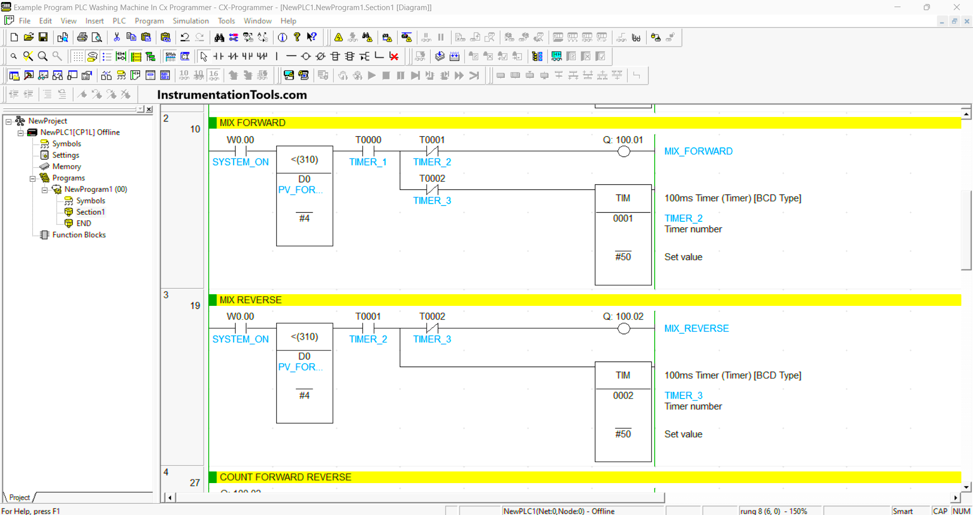
RUNG 2 (MIX FORWARD)
In this Rung, the Output MIX_FORWARD (100.01) will be ON when NO contacts of the memory bits SYSTEM_ON (W0.00) and TIMER_1 (T0000) in HIGH state and the value of memory word PV_FORWARD_REVERSE (D0) is less than “4”.
Timer TIMER_2 (T0001) will count for 5 seconds, when Timer TIMER_2 (T0001) finishes counting, the Output MIX_FORWARD (100.01) will be OFF because of the Interlock. Timer TIMER_2 (T0001) will be OFF when NC contact of TIMER_3 (T0002) is in the HIGH state.
RUNG 3 (MIX REVERSE)
In this Rung, the Output MIX_REVERSE (100.02) will be ON when NO contact of the memory bit SYSTEM_ON (W0.00) and Timer TIMER_2 (T0001) in a HIGH state and the value of memory word PV_FORWARD_REVERSE (D0) is less than “4”.
Timer TIMER_3 (T0002) will count for 5 seconds, when Timer TIMER_3 (T0002) finishes counting, the Output MIX_REVERSE (100.02) will be OFF because of the Interlock.
RUNG 4 (COUNT FORWARD REVERSE)
In this Rung, when NO contact of the MIX_REVERSE (100.02) in the HIGH state then the value in memory word PV_FORWARD_REVERSE (D0) will increase (+1) using the Binary Increment Instruction.
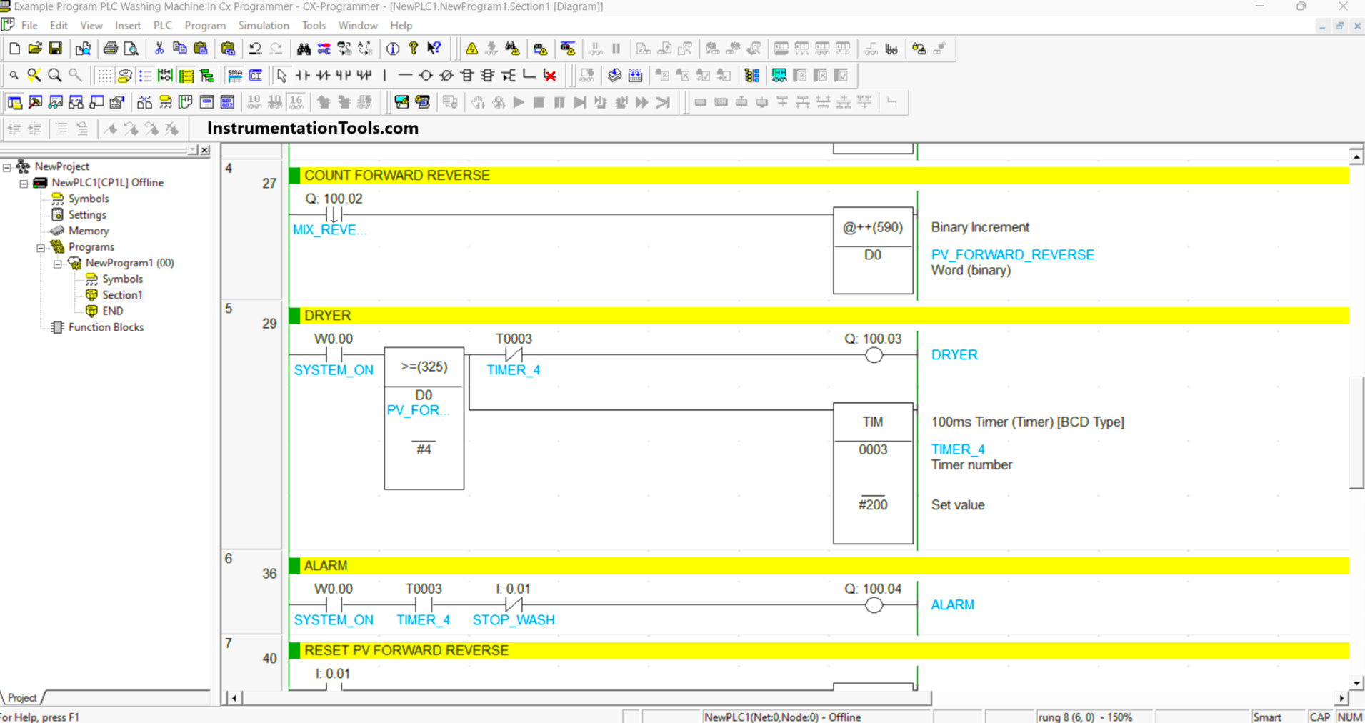
RUNG 5 (DRYER)
In this Rung, the Output DRYER (100.03) will be ON when NO contact of the memory bit SYSTEM_ON (W0.00) in a HIGH state and value in the memory word PV_FORWARD_REVERSE (D0) is less than or equal to “4”.
Timer TIMER_4 (T0003) will count for 20 seconds, when Timer TIMER_4 (T0003) finishes counting, the Output DRYER (100.03) will be OFF because of the Interlock.
RUNG 6 (ALARM)
The output ALARM (100.04) will be ON when NO contacts of the memory bits SYSTEM_ON (W0.00) and TIMER_4 (T0003) in the HIGH state.
The output ALARM (100.04) will be OFF when the STOP_WASH (0.01) button is Pressed.
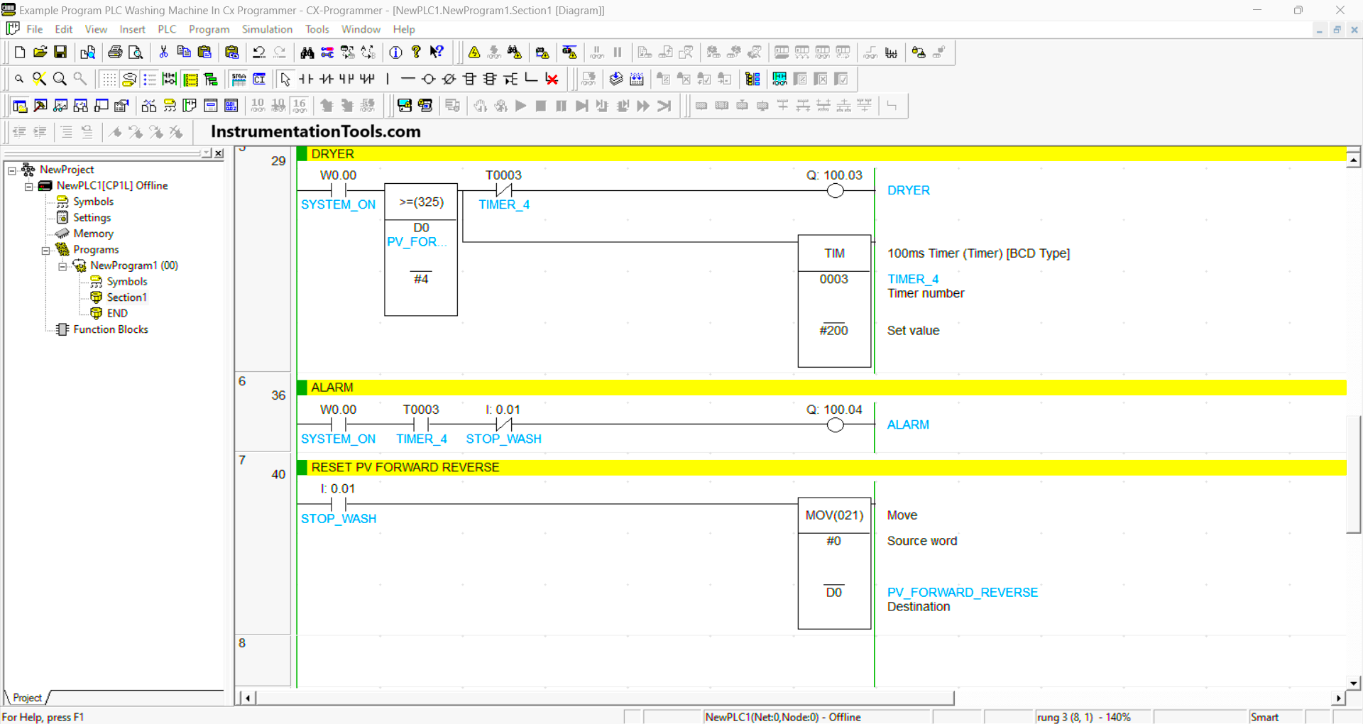
RUNG 7 (RESET PV FORWARD REVERSE)
In this Rung, when the STOP_WASH (0.01) button is pressed, the memory word PV_FORWARD_REVERSE (D0) will become zero value “0”. This is because the MOV instruction moves the zero value “0” to the memory word PV_FORWARD_REVERSE (D0).
Read Next:
- PLC Product Sticker Machine with Weighing
- Automatic Car Washing using PLC Program
- Waste-Burning System OMRON PLC Logic
- Water Pump PLC Program CX-Programmer
- Automate Batch Mixing with Repeated Cycle