Inst ToolsInst ToolsInst Tools
  • Courses
  • Automation
    • PLC
    • Control System
    • Safety System
    • Communication
    • Fire & Gas System
  • Instrumentation
    • Design
    • Pressure
    • Temperature
    • Flow
    • Level
    • Vibration
    • Analyzer
    • Control Valve
    • Switch
    • Calibration
    • Erection & Commissioning
  • Interview
    • Instrumentation
    • Electrical
    • Electronics
    • Practical
  • Q&A
    • Instrumentation
    • Control System
    • Electrical
    • Electronics
    • Analog Electronics
    • Digital Electronics
    • Power Electronics
    • Microprocessor
  • Request
Search
  • Books
  • Software
  • Projects
  • Process
  • Tools
  • Basics
  • Formula
  • Power Plant
  • Root Cause Analysis
  • Electrical Basics
  • Animation
  • Standards
  • 4-20 mA Course
  • Siemens PLC Course
Reading: What is NAMUR NE 43?
Share
Font ResizerAa
Inst ToolsInst Tools
Font ResizerAa
  • Courses
  • Design
  • PLC
  • Interview
  • Control System
Search
  • Courses
  • Automation
    • PLC
    • Control System
    • Safety System
    • Communication
    • Fire & Gas System
  • Instrumentation
    • Design
    • Pressure
    • Temperature
    • Flow
    • Level
    • Vibration
    • Analyzer
    • Control Valve
    • Switch
    • Calibration
    • Erection & Commissioning
  • Interview
    • Instrumentation
    • Electrical
    • Electronics
    • Practical
  • Q&A
    • Instrumentation
    • Control System
    • Electrical
    • Electronics
    • Analog Electronics
    • Digital Electronics
    • Power Electronics
    • Microprocessor
  • Request
Follow US
All rights reserved. Reproduction in whole or in part without written permission is prohibited.
Inst Tools > Blog > Standards > What is NAMUR NE 43?

What is NAMUR NE 43?

Last updated: July 11, 2020 12:45 pm
Editorial Staff
Standards
2 Comments
Share
3 Min Read
SHARE

Well NAMUR NE 43 is in trend to be mentioned with 4-20 mA output.

Contents
NAMUR NE 431. Transmitter Failure Identification :-2. Process Variable has gone under-Range or Over Range :-Under-Range :-Over-Range:-NOW Physical Problems :-3. Short Circuited wire :-4. Open Wire :-

It is said it increases diagnostic features ?

But what can you do more in 4-20 mA ?

NAMUR NE 43

Well as per API 551 recommendation following things can be distinguished when signal levels are properly defined :-

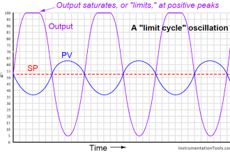
  1. When the process variable has increased beyond transmitter calibrated range and transmitter has gone into saturation
  2. When the transmitter is faulty and it is not the process variable range that is driving transmitter to saturation
  3. When the transmitter wire is short circuited
  4. When the Transmitter wire is open

How this happens !

1. Transmitter Failure Identification :-

On failure of transmitter , The Transmitter is configured to output LOW or HIGH

This LOW Range can be between 3.6 to 3.8 mA

This HIGH Range can be between 20.5 to 22 mA

NOTE:-This between means we select a value as per our requirement .

E:G :- Factory setting for E+H Transmitter is 22mA

2. Process Variable has gone under-Range or Over Range :-

Under-Range :-

Between 3.8 to 4 mA would state that process variable has gone below the calibrated range but THE TRANSMITTER IS NOT FAULTY

Over-Range:-

Between 20 to 20.5 mA would state that process variable has gone above the calibrated range but THE TRANSMITTER IS NOT FAULTY

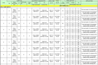
The below table from API 551 makes it clear

NAMUR NE 43

NOW Physical Problems :-

Suppose the Transmitter is working fine

Also the process variable is between the calibrated range .

BUT some physical limitation occurs .

3. Short Circuited wire :-

Suppose the Transmitter is working fine

Also the process variable is between the calibrated range .

BUT the wire is short circuited so a high amount of Current will flow through the circuit .

This high amount of current is defined as Greater than 22 mA (As mentioned in API 551 you could change as per your preference)

Note :- this definition differs from project to project after what predetermined value do you want it to detect a short circuit.

4. Open Wire :-

What if the wire comes out , gets cut etc..

This is also on of the driving factors we have 4 mA as starting and not 0 mA .Live Zero Concept .

Open field is defined as 0 to 3.6 . ( this is if wire is partially cut or completely cut )

Thanks for reading !!

PS : As always, This is as per best of my understanding !

Author : Asad Shaikh

Profile : Linkedin

Articles You May Like :

Basics of Loop Checks

3-15 psi to 4-20 mA Conversion

4–20 mA Process Control Loop

HART Communication Protocol

Live Zero in 4-20 mA Current Loop

Don't Miss Our Updates
Be the first to get exclusive content straight to your email.
We promise not to spam you. You can unsubscribe at any time.
Invalid email address
You've successfully subscribed !

Continue Reading

Explosive Atmospheres & Hazardous Classification
Pre-Startup Safety Review (PSSR)
Instrumentation Standards Questions and Answers
Purge & Pressurization Systems Interview Questions
Analytical Standards
Purging of Instruments
Share This Article
Facebook Whatsapp Whatsapp LinkedIn Copy Link
Share
2 Comments
  • Dave says:
    December 22, 2019 at 5:34 am

    I think 3.8 to 3.6 and 20.5 to 22 are not the correct ranges. NAMUR compliant failed state should be represented by an output below 3.6 or above 21.0. There is different / conflicting info on this topic, and I am going to get a copy of the NE43 to verify this, but I think you should check your values.

    Reply
    • Zhou Weiyong says:
      August 14, 2024 at 8:06 am

      Agree with you, but different vendor has different setting value for hardware fault ,anyway the value should be below 3.6 or above 21.0.

      Reply

Leave a Reply Cancel reply

Your email address will not be published. Required fields are marked *

Stay Connected

128.3kFollowersLike
69.1kFollowersFollow
210kSubscribersSubscribe
38kFollowersFollow

Categories

Explore More

Instrumentation Engineering Standards Questions & Answers
NAMUR NE107 Standard
Identification of Equipment
What is HAZOP ?
ATEX Ratings, Intrinsic Safety, Hazardous Areas and Explosive Atmospheres
Gas Detectors Standards
Intrinsic Safety Protection ia and ib
Difference between Explosion Proof and Intrinsically Safe

Keep Learning

IEC 60909 and IEC 61363 for Short Circuit

Difference Between IEC 60909 and IEC 61363 for Short Circuit

IEC Area Classification System

Ex ic Intrinsic safety Standard

Hazardous Area Terminology

Hazardous Area Terminology

NFPA Standards (National Fire Protection Association Standards)

NFPA Standards (National Fire Protection Association Standards)

UL 489 Circuit Breaker

Difference Between UL489 and UL1077

explosion-proof electrical enclosures

Classified Areas and Electrical Safety Measures

Basics of Explosion Protection

Basics of Explosion Protection

Instrumentation Cables Testing Standards

Instrumentation Cables Testing Standards

Learn More

factorytalk view studio hmi

How to Create Templates in FactoryTalk View Studio?

Chromatography Questions & Answers

Chromatography Questions & Answers

Counter Count Down Bit

Down Counter PLC Program

Do’s and Don'ts in PLC

Do’s and Don’ts in PLC

CIPP Lining Procedure

What is CIPP Lining? Procedure and Advantages

Magnetic Float Level Switch Principle

Magnetic Float Level Switch Installation Techniques

Power Systems Questions & Answers

Power Systems MCQ Series 14

Feedback Characteristics of Control Systems

Feedback and Non-feedback Systems Objective Questions

Menu

  • About
  • Privacy Policy
  • Copyright

Quick Links

  • Learn PLC
  • Helping Hand
  • Part Time Job

YouTube Subscribe

Follow US
All rights reserved. Reproduction in whole or in part without written permission is prohibited.
Welcome Back!

Sign in to your account

Username or Email Address
Password

Lost your password?