Inst ToolsInst ToolsInst Tools
  • Courses
  • Automation
    • PLC
    • Control System
    • Safety System
    • Communication
    • Fire & Gas System
  • Instrumentation
    • Design
    • Pressure
    • Temperature
    • Flow
    • Level
    • Vibration
    • Analyzer
    • Control Valve
    • Switch
    • Calibration
    • Erection & Commissioning
  • Interview
    • Instrumentation
    • Electrical
    • Electronics
    • Practical
  • Q&A
    • Instrumentation
    • Control System
    • Electrical
    • Electronics
    • Analog Electronics
    • Digital Electronics
    • Power Electronics
    • Microprocessor
  • Request
Search
  • Books
  • Software
  • Projects
  • Process
  • Tools
  • Basics
  • Formula
  • Power Plant
  • Root Cause Analysis
  • Electrical Basics
  • Animation
  • Standards
  • 4-20 mA Course
  • Siemens PLC Course
Reading: Monitor and Modify Variables in Simatic Manager
Share
Font ResizerAa
Inst ToolsInst Tools
Font ResizerAa
  • Courses
  • Design
  • PLC
  • Interview
  • Control System
Search
  • Courses
  • Automation
    • PLC
    • Control System
    • Safety System
    • Communication
    • Fire & Gas System
  • Instrumentation
    • Design
    • Pressure
    • Temperature
    • Flow
    • Level
    • Vibration
    • Analyzer
    • Control Valve
    • Switch
    • Calibration
    • Erection & Commissioning
  • Interview
    • Instrumentation
    • Electrical
    • Electronics
    • Practical
  • Q&A
    • Instrumentation
    • Control System
    • Electrical
    • Electronics
    • Analog Electronics
    • Digital Electronics
    • Power Electronics
    • Microprocessor
  • Request
Follow US
All rights reserved. Reproduction in whole or in part without written permission is prohibited.
Inst Tools > Blog > PLC Tutorials > Monitor and Modify Variables in Simatic Manager

Monitor and Modify Variables in Simatic Manager

Last updated: March 4, 2021 11:32 am
Editorial Staff
PLC Tutorials
No Comments
Share
2 Min Read
SHARE

In this article, I will show you how to monitor and modify variables from the hardware configuration using the Siemens Simatic manager.

Monitor and Modify Variables

Follow the below steps to monitor and modify variables from the hardware configuration.

Step 1:

Open Simatic manager. Select the “CPU” and double click on “hardware” to enter in to hardware environment.
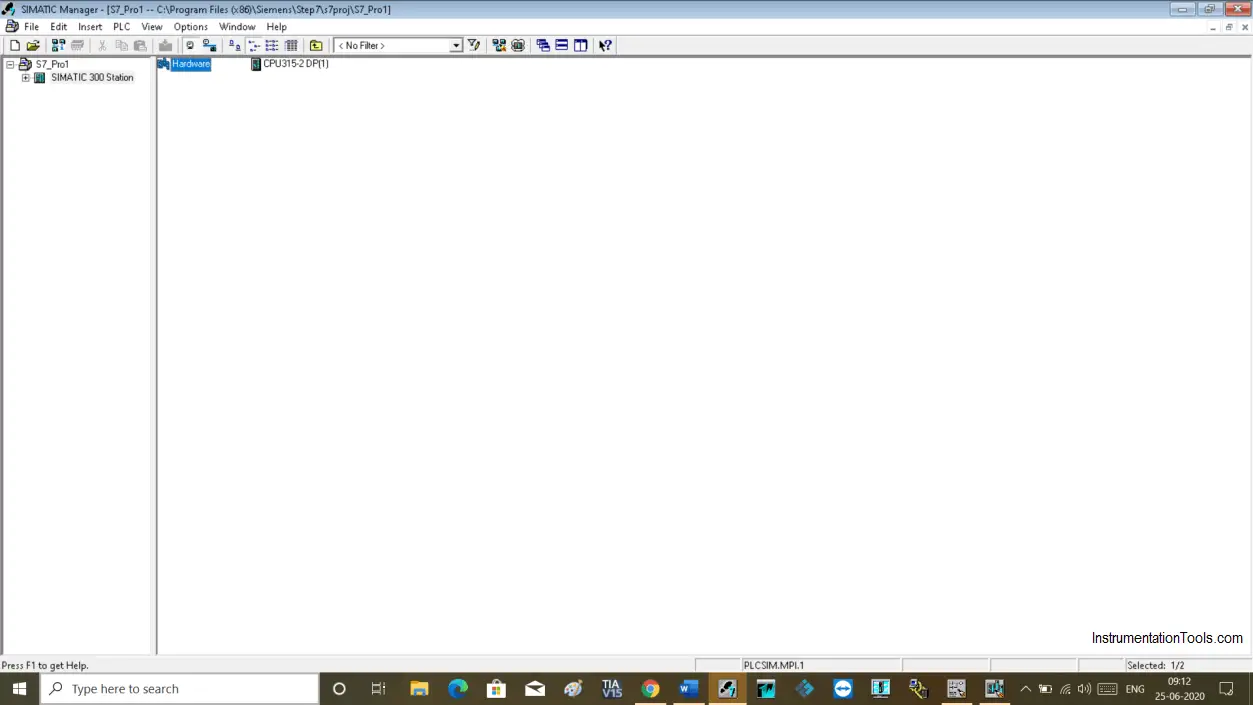
Modify variables from hardware configuration

Step 2:

The following hardware configuration window will open up.
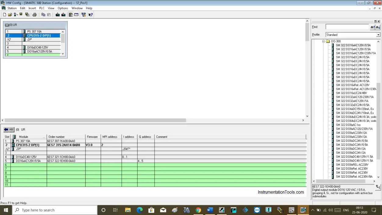
Simatic Hardware Configuration

Step 3:

To monitor or modify a variable, select digital input or output card and do right-click to open properties as you can see in the below window.

Click on monitor/modify to open a new window.

To monitor or modify a variable, download project to the simulator.
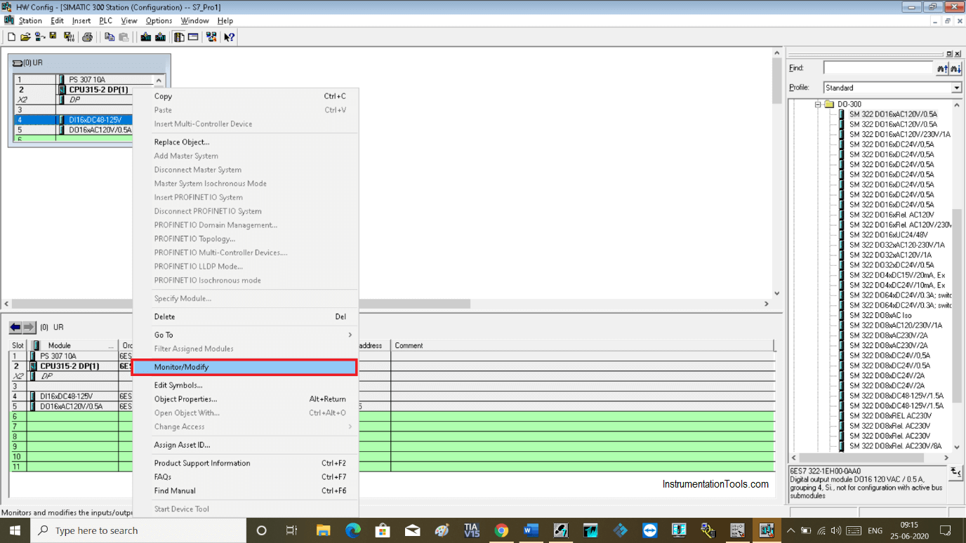
Monitor or Modify Variables

Step 4:

The following window will open up. Here, as I have selected digital inputs, it will only show digital inputs.
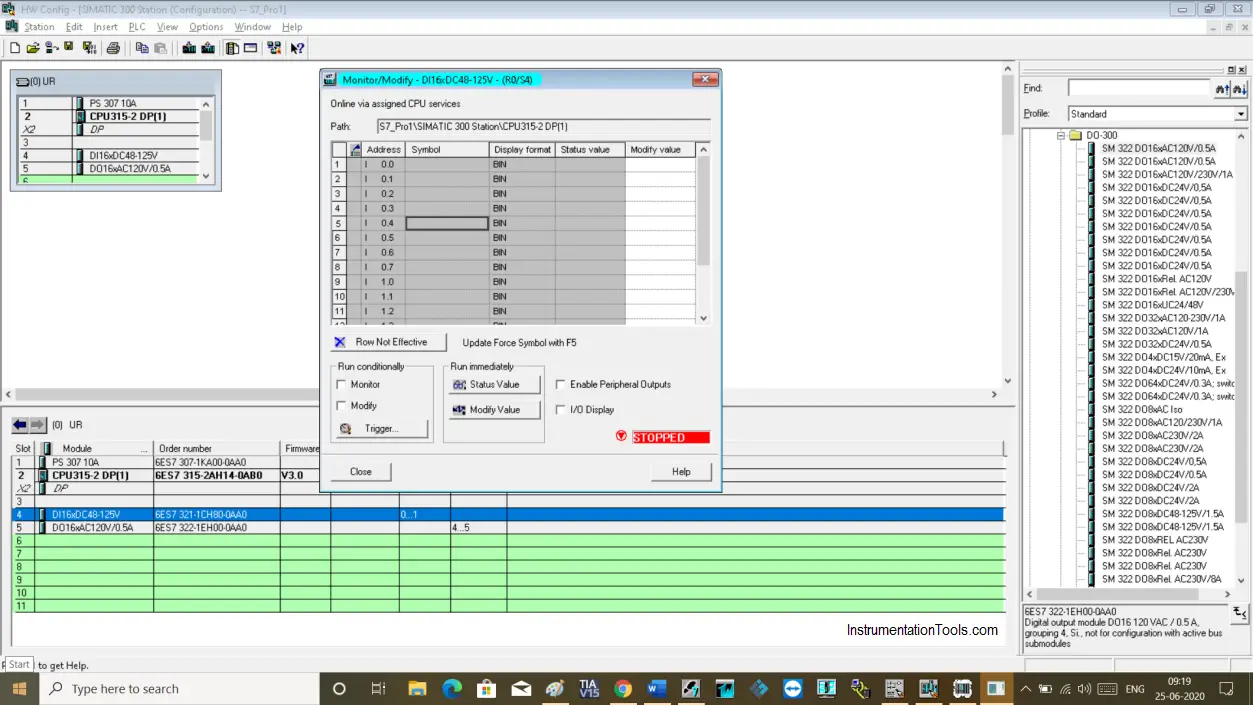
Simatic 300 Station Configuration

Step 5:

To monitor the input variable, do checkmark as shown in the below window.

Keep the program in monitor mode to see the status of the input variable.
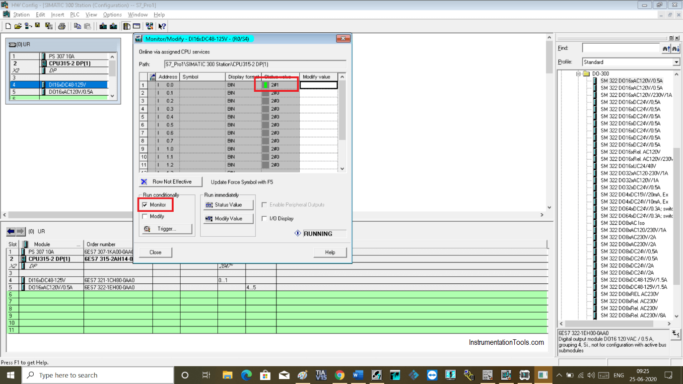
Monitor the input variable in Simatic Manager

Step 6:

Now to modify the value or to change the status of the input variable, use the modify option.

To modify a value, click on modify value and write “0” or “1” then click on “modify value” to make changes.
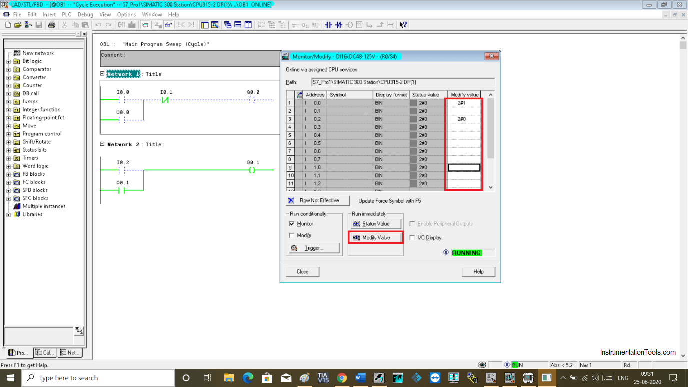
Simatic Modify Value

Step 7:

Under modify and monitor option, there is one more tab “ trigger” is available.

Clicking on the trigger will open up a new window.

Here, as you can see triggering options for modifying and monitoring value.

You can set it as per your requirement for a single scan cycle or every scan cycle.
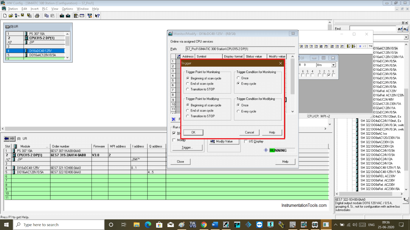
Trigger Point for Monitoring

Author: Suhel Patel

If you liked this article, then please subscribe to our YouTube Channel for PLC and SCADA video tutorials.

You can also follow us on Facebook and Twitter to receive daily updates.

Read Next:

  • RSLogix 500 PID Instruction
  • Siemens S7 300 CPU Status
  • Rewire Tool in Simatic Manager
  • Trace Function in Tia Portal
  • Simatic Manager New Project
Don't Miss Our Updates
Be the first to get exclusive content straight to your email.
We promise not to spam you. You can unsubscribe at any time.
Invalid email address
You've successfully subscribed !

Continue Reading

Siemens TIA Portal Elevator System with Safety Features
Unknown Do’s Need to Know as a PLC Programmer
Programming Schneider PLC Manual Sequential Machine
How Modbus is used in Industrial Networks?
Types of Digital Outputs in PLC
What is Marshalling Cabinet?
Share This Article
Facebook Whatsapp Whatsapp LinkedIn Copy Link
Share
Leave a Comment

Leave a Reply Cancel reply

Your email address will not be published. Required fields are marked *

Stay Connected

128.3kFollowersLike
69.1kFollowersFollow
210kSubscribersSubscribe
38kFollowersFollow

Categories

Explore More

Step by Step Guidelines for Downloading Free PLC software
PLC Program for 2 Push buttons to Control 1 Output
Troubleshoot the Status of a PLC Via CPU Indicators
One-Shot Rising and Falling Edge Instructions in Rockwell PLC
Troubleshoot Allen Bradley PLC Logic
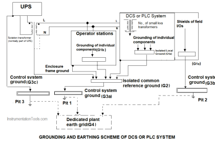
DCS versus PLC Architecture
Automation System for Hazardous Environments
Demo of a SCADA Software – Level Control System

Keep Learning

PLC Ladder Logic Door Open and Closing System

Which Language is Best for PLC Programming?

IP Address Change in Simatic

PLC Configuration of Profinet I/O System

Control Panel

What is a Control Panel and its types?

Interlock Philosophy

Types of Interlocks

Omron PLC programs

Daily Alarm PLC Program using Real-Time Clock

PLC Math instructions

PLC Math instructions

Types of Switches

Electrical Switches Principle & Types

PLC Batch System for 4 Tanks Mixing using CX-Programmer

PLC Batch System for 4 Tanks Mixing using CX-Programmer

Learn More

D’Arsonval Movement

D’Arsonval Movement

Electric Circuits Objective Questions

Electric Circuits Objective Questions – Set 3

Standard Operating Procedure

What is SOP and How to Create an SOP?

Ladder Logic Counters Instruction

Up Counter PLC Program

Power Systems Questions & Answers

Power Systems MCQ Series 1

Single Phase Half-controlled Rectifier RL Load With FD

Phase-Controlled Half-Wave Rectifier With Freewheeling Diode

Hazards of Compressed Air

Hazards of Compressed Air

Power Electronics Objective Questions

Three Phase Converters Objective Questions

Menu

  • About
  • Privacy Policy
  • Copyright

Quick Links

  • Learn PLC
  • Helping Hand
  • Part Time Job

YouTube Subscribe

Follow US
All rights reserved. Reproduction in whole or in part without written permission is prohibited.
Welcome Back!

Sign in to your account

Username or Email Address
Password

Lost your password?