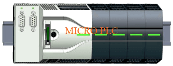
Write the steps for Micro PLC hardware configuration for Analog Modules like AI, AO and Digital signal modules like DI, DO.

For this plc configuration, we will use the Simatic manager software. The configuration of the micro PLC can be done by using Profinet I/O system in the Simatic manager.
Load and configure the Profinet GSD file and save it in an appropriate directory. Start the siemens configurator and install a new GSD file in the software.
After configuration and installation, the hardware configuration file will be available in the hardware catalog.
Download: TIA Portal Free Version
As shown in the below method, we can configure micro PLC in Simatic manager.
For example, we have considered a micro PLC M13C. Open Simatic manager and configure S7-300 PLC in the hardware configuration. For micro PLC, take Profinet I/O supported CPU.
As shown in below figure 1, we can configure CPU 314C-2PN/DP in the hardware configurator window. This CPU can be selected from the hardware catalog. Add a Profinet bus in CPU as shown in figure 1.
After adding an ethernet I/O bus micro PLC can be configured on an ethernet bus.
As shown in below figure 2, after the configuration of PLC we can take micro PLC from the hardware catalog.
Select the VIPA micro system folder and select the M13C CPU.
Add Digital input, digital output, analog input and analog output modules in micro PLC.
After the configuration of PLC as shown in figure 1, we can add a signal module in PLC as per requirement.
For example, here we used 1 DI module, 1 DO module,1 AI module, and 1 AO module.
First, click on PLC and search DI module from the catalog and add it as shown in below figure 3.
Right-click on row no 1 to add the module.
As shown in below figure 4, we can add the DI module (M21) by selecting AI folder, the same procedure for all other modules.
Note: – This is the simple hardware configuration explanation; we can use this concept in other examples also.
If you liked this article, then please subscribe to our YouTube Channel for PLC and SCADA video tutorials.
You can also follow us on Facebook and Twitter to receive daily updates.
Read Next:
DeltaV DCS System Configuration
Learn an example PLC program to control a pump based on level sensors using ladder…
In the PLC timer application for security camera recording, when motion is detected then camera…
In this example, we will learn batch mixing with PLC ladder logic program using timer…
This PLC example on manufacturing line assembly is an intermediate-level PLC program prepared for the…
In this article, you will learn the PLC programming example with pushbutton and motor control…
This article teaches how to convert Boolean logic to PLC programming ladder logic with the…