Inst ToolsInst ToolsInst Tools
  • Courses
  • Automation
    • PLC
    • Control System
    • Safety System
    • Communication
    • Fire & Gas System
  • Instrumentation
    • Design
    • Pressure
    • Temperature
    • Flow
    • Level
    • Vibration
    • Analyzer
    • Control Valve
    • Switch
    • Calibration
    • Erection & Commissioning
  • Interview
    • Instrumentation
    • Electrical
    • Electronics
    • Practical
  • Q&A
    • Instrumentation
    • Control System
    • Electrical
    • Electronics
    • Analog Electronics
    • Digital Electronics
    • Power Electronics
    • Microprocessor
  • Request
Search
  • Books
  • Software
  • Projects
  • Process
  • Tools
  • Basics
  • Formula
  • Power Plant
  • Root Cause Analysis
  • Electrical Basics
  • Animation
  • Standards
  • 4-20 mA Course
  • Siemens PLC Course
Reading: Micro PLC Hardware Configuration
Share
Font ResizerAa
Inst ToolsInst Tools
Font ResizerAa
  • Courses
  • Design
  • PLC
  • Interview
  • Control System
Search
  • Courses
  • Automation
    • PLC
    • Control System
    • Safety System
    • Communication
    • Fire & Gas System
  • Instrumentation
    • Design
    • Pressure
    • Temperature
    • Flow
    • Level
    • Vibration
    • Analyzer
    • Control Valve
    • Switch
    • Calibration
    • Erection & Commissioning
  • Interview
    • Instrumentation
    • Electrical
    • Electronics
    • Practical
  • Q&A
    • Instrumentation
    • Control System
    • Electrical
    • Electronics
    • Analog Electronics
    • Digital Electronics
    • Power Electronics
    • Microprocessor
  • Request
Follow US
All rights reserved. Reproduction in whole or in part without written permission is prohibited.
Inst Tools > Blog > PLC Tutorials > Micro PLC Hardware Configuration

Micro PLC Hardware Configuration

Last updated: March 4, 2021 2:40 pm
Editorial Staff
PLC Tutorials
No Comments
Share
3 Min Read
SHARE

 Write the steps for Micro PLC hardware configuration for Analog Modules like AI, AO and Digital signal modules like DI, DO.

Contents
Micro PLCConfiguration:-

Micro PLC

Micro PLC Hardware Configuration

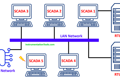
For this plc configuration, we will use the Simatic manager software. The configuration of the micro PLC can be done by using Profinet I/O system in the Simatic manager.

Load and configure the Profinet GSD file and save it in an appropriate directory. Start the siemens configurator and install a new GSD file in the software.

After configuration and installation, the hardware configuration file will be available in the hardware catalog.

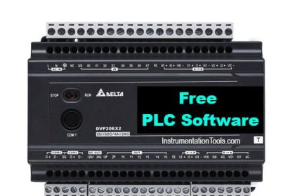
Download: TIA Portal Free Version

As shown in the below method, we can configure micro PLC in Simatic manager.

Configuration:-

For example, we have considered a micro PLC M13C. Open Simatic manager and configure S7-300 PLC in the hardware configuration. For micro PLC, take Profinet I/O supported CPU.

As shown in below figure 1, we can configure CPU 314C-2PN/DP in the hardware configurator window. This CPU can be selected from the hardware catalog. Add a Profinet bus in CPU as shown in figure 1.

After adding an ethernet I/O bus micro PLC can be configured on an ethernet bus.

Micro PLC Ethernet Bus Configuration

As shown in below figure 2, after the configuration of PLC we can take micro PLC from the hardware catalog.

Select the VIPA micro system folder and select the M13C CPU.

VIPA Micro System

Add Digital input, digital output, analog input and analog output modules in micro PLC.

After the configuration of PLC as shown in figure 1, we can add a signal module in PLC as per requirement.

For example, here we used 1 DI module, 1 DO module,1 AI module, and 1 AO module.

First, click on PLC and search DI module from the catalog and add it as shown in below figure 3.

Right-click on row no 1 to add the module.

DI Module Configuration in Micro PLC

As shown in below figure 4, we can add the DI module (M21) by selecting AI folder, the same procedure for all other modules.

Micro PLC Hardware Configuration

Note: – This is the simple hardware configuration explanation; we can use this concept in other examples also.

Author: Bhavesh

If you liked this article, then please subscribe to our YouTube Channel for PLC and SCADA video tutorials.

You can also follow us on Facebook and Twitter to receive daily updates.

Read Next:

Siemens S7 1200 PLC

DeltaV DCS System Configuration

Logic Gates and Truth table

Redundant Controller in PLC

PLC Cables Wiring Technique

Don't Miss Our Updates
Be the first to get exclusive content straight to your email.
We promise not to spam you. You can unsubscribe at any time.
Invalid email address
You've successfully subscribed !

Continue Reading

Ladder Logic Example of Two Motors Interlinked with another Motor
Overview of Industrial Control Systems
PLC Program for Fish Feeding System
Motor Control Circuits
PLC to PLC Communication using S7 Connection PUT & GET Instructions
Free SCADA Software Download
Share This Article
Facebook Whatsapp Whatsapp LinkedIn Copy Link
Share
Leave a Comment

Leave a Reply Cancel reply

Your email address will not be published. Required fields are marked *

Stay Connected

128.3kFollowersLike
69.1kFollowersFollow
210kSubscribersSubscribe
38kFollowersFollow

Categories

Explore More

PLC Sequence Programming Ladder Logic
PLC Counter Instructions
Mitsubishi PLC Programming Tutorials
PLC Question Bank
What is Live Zero in 4-20 mA Current Loop?
#12 PLC Best Practices – Validate Inputs based on Physical Plausibility
Daily Alarm PLC Program using Real-Time Clock
PLC Selective Execution of the Application – Example Program

Keep Learning

Siemens PLC Course for Beginners

Siemens PLC Course for Beginners: Problems and Solutions

Site Acceptance Test (SAT) of PLC System

PLC System Site Acceptance Test (SAT)

Intrinsic Safety Barriers

Intrinsically Safe Barriers Questions and Answers

Delta HMI and VFD Control with Modbus

Delta HMI and VFD Control with Modbus

PROFIBUS is also a Master Slave protocol

Compare Modbus, Fieldbus, and Profibus

Proper Earthing Practices Used for PLC Control Panel

Proper Earthing Practices Used for PLC Control Panel

How CPU Execute Program in Siemens PLC?

How CPU Execute Program in Siemens PLC?

Tanks Draining Control in PLC using Functional Block Diagram

Tanks Draining Control in PLC using Functional Block Diagram

Learn More

Programmable Logic Controller Quiz

Programmable Logic Controller Quiz

CODESYS open source PLC software

What is CODESYS? Why Do You Need to Learn it?

Gas Suppression System

What is Gas Suppression Systems ?

PLC automation timers and counters

Medium-Level PLC Exercise for Students in Automation

Shunt-Wound DC Motor

Shunt-Wound Motor Operation

Operator Interface for SCADA System

Operator Interface for SCADA System

Fluorescent Screen of CRT

CRT Fluorescent Screen

Read Temperature in PLC

PLC Program to Read Temperature in PLC

Menu

  • About
  • Privacy Policy
  • Copyright

Quick Links

  • Learn PLC
  • Helping Hand
  • Part Time Job

YouTube Subscribe

Follow US
All rights reserved. Reproduction in whole or in part without written permission is prohibited.
Welcome Back!

Sign in to your account

Username or Email Address
Password

Lost your password?