Here in this article, we discussed the general testing or healthiness checking procedure of a Manual Call Point (MCP) of fire alarm panel.
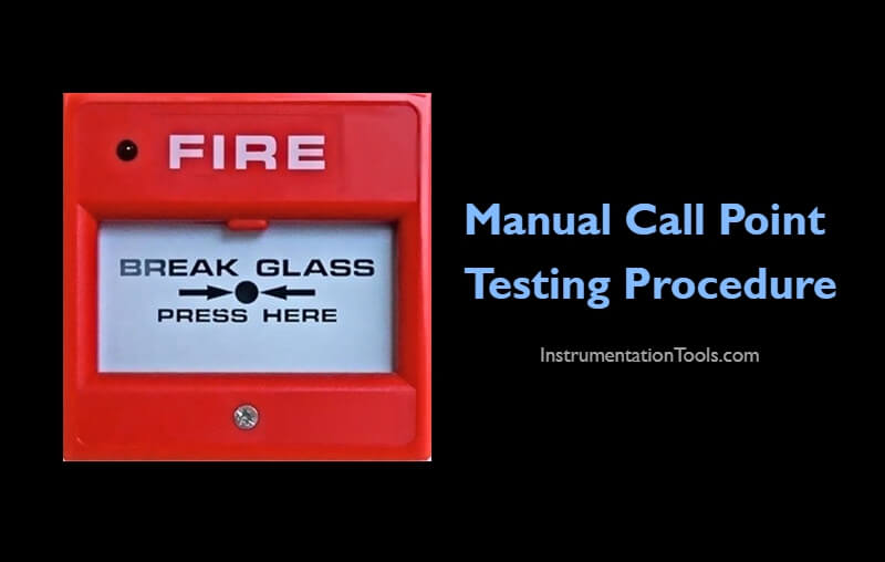
Manual Call Point Testing Procedure
Before starting the job, take the proper work permit and inform to all the respective departments. Also, do force the respective logics or interlocks if any (like fire suppression systems activation etc)
- Remove all the screws and remove the glass cap from MCP.
- After removing the glass cap from MCP, the switch inside it activates so alarm appears on Fire alarm panel and the hooter is activated.
- Acknowledge the alarm or silence the hooter on the fire alarm panel.
- Note down the alarm tag and descriptions from the HMI or workstation. The alarm details must match with the MCP tag number and installed location.
- Confirm the MCP activation status from the respective graphics page. You have to visually identify the color change signals of the respective MCP on the graphics.
- Check the + 36 Volts DC Supply on Monitor Module between terminal 1 and 2. (This is the circuit module inside the MCP).
- Check all the wire connections on Monitor Module, the push button contact if it found loose then tighten them fully.
- Ensure resistor leads are completely tightened on to the terminals of the circuit in MCP.
- Clean the MCP dust by brush and cotton cloth.
- Fix the glass cap of MCP and fix all screws. It should be fully tightened. If it is loose alarm reappears.
- Reset the alarm signal from the Fire Alarm Panel.
- Now MCP is working now in Normal condition.
- Repeat the above procedure for all the remaining MCP’s.
- Normalize the forced interlocks or logics if any.
- Close the work permit.
Note: The mentioned voltages, terminals, circuit module names may change as per the vendor or model of the Manual Call Point.
Author: V Hemanth
Read Next:
- Fire Detectors Questions
- Linear Heat Detectors
- Thermal Detectors Principle
- Fire Alarm Control Panel
- Types of Fire Detectors