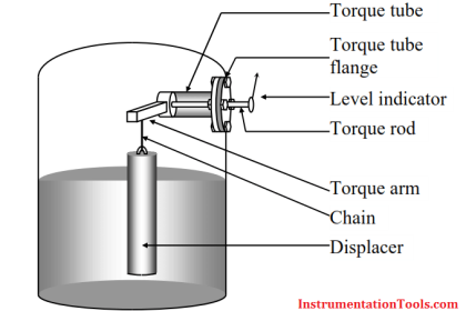
Magnetic Level Gauge

Inside the indicator tube is a lightweight magnetized indicator or series of metallic flags. The indicator is magnetically coupled to the float and moves up and down with the liquid level. The indicator allows the operator to read the level from more than 100 feet away. The only moving parts are the float and the indicator.
Theory :
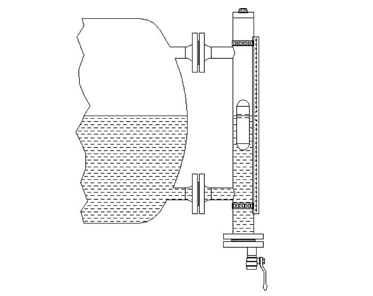
Magnetic level gauges work on the principle of communicating vessels, therefore the level in the measuring chamber will be the same as the level in the vessel. The measuring chamber is fitted with a float, which has a magnet inside. The float with magnet will float on the medium and the magnet in the float will turn the flaps of the indicating rail.
The float in the measuring tube is standard not pressurized and has no magnetic or mechanical guidance. This construction makes the float less dangerous than a float which is standard pressurized. When necessary Hadro can produce a pressurized float.
With the below mentioned process conditions it is possible to select a float which will float on the medium.
- Medium
- Density
- Working pressure
- Temperature
Each flap in the indicating rail is fitted with a permanent magnet which makes this level gauge unaffected by shocks, vibrations and high temperatures. Also moisture and / or an aggressive environment are no problem for this level gauge.
This magnetic level gauge is available with plastic or stainless steel flaps. The flaps can be placed in a plastic, aluminium or stainless steel housing.
Because of the construction of the flaps, one side white and on the other red / orange it is possible to see the level over a greater distance or in darker places.
With the available “Pointers” it is possible to set the visual limits on the indicating rail on every level you require.
When the magnetic level gauge is fitted with magnetic switches it is possible to get a signal. With more switches you can make a pump control (pump on / off) and / or create a high / low alarm. Beside or instead of level switches a reedchain transmitter can be mounted, this reedchain has an standard output signal of 4-20 mA.
Magnetic level gauge are also suitable for interface reading. The float will sink into the medium with the lower density and will float on the medium with the higher density.
Advantages
- Standard unpressurised floatsystem
- Float without mechanical or magnetic guide rails
- Fully corrosion resistant system
- Measurement is unaffected by pressure, vacuum, temperature, foam and viscosity
- Minimum sensitivity to density variations
- Permanent indication without external power supply
- Low temperature version is fitted with ice free indication strip
- Fully adjustable switches
- Back lighting is unnecessary
- Eccentric drain cannot blocked by the float
Available floats
All the magnetic level gauges are fitted with a float. This float is standard in stainless steel, but the float is also available in Titanium or Hastelloy. The float must have enough buoyancy and the magnet must be fitted at the right position inside the float. So it is always important to select a float which is suitable for the process conditions.
In order to select the correct float the following process conditions are necessary.
- Medium
- Density
- Working pressure
- Operating temperature
The lowest density, for which we can supply a float is 380 kg/m3 but this is depending on the before mentioned process conditions.
When a fluid is very aggressive we can also coat the float with a suitable lining. When we have a choice between an open float or a pressurised float we prefer the pressurized float. Because the open float will eventually sink, condensate will build up inside the open float. For example our pressurized floats are suitable for 208 bar at 375°C with a density of 650 kg/m3 .
The float inside a magnetic level gauge can be fitted with a torriodal (360°) magnet or a magnetic bar. All our floats are fitted standard with a torriodalmagnet, because a float with a magnetic bar can loose there guidance/ indication rail by rapid movement inside the level gauge. As a result the magnetic level gauge will not work properly for a while. Torriodalmagnets are not affected by rapid movements of the float and can move freely inside the level gauge. This is also why you can place a level switch at all the sides you want.
Switches
When you mount a magnetic switch on the level gauge it is possible to get a signal. With more switches you can make a pump control (pump on / off) and / or obtain a high / low alarm. We can supply general purpose switches, switches for hazardous areas, or switches suitable for marine applications.
Also Read: Working Principle of Different Level Indicators


dear, sir thnx……..very much for the basic of level measurment,,,,,thank’s again