Inst ToolsInst ToolsInst Tools
  • Courses
  • Automation
    • PLC
    • Control System
    • Safety System
    • Communication
    • Fire & Gas System
  • Instrumentation
    • Design
    • Pressure
    • Temperature
    • Flow
    • Level
    • Vibration
    • Analyzer
    • Control Valve
    • Switch
    • Calibration
    • Erection & Commissioning
  • Interview
    • Instrumentation
    • Electrical
    • Electronics
    • Practical
  • Q&A
    • Instrumentation
    • Control System
    • Electrical
    • Electronics
    • Analog Electronics
    • Digital Electronics
    • Power Electronics
    • Microprocessor
  • Request
Search
  • Books
  • Software
  • Projects
  • Process
  • Tools
  • Basics
  • Formula
  • Power Plant
  • Root Cause Analysis
  • Electrical Basics
  • Animation
  • Standards
  • 4-20 mA Course
  • Siemens PLC Course
Reading: Magnetic Float Level Switch Installation Techniques
Share
Font ResizerAa
Inst ToolsInst Tools
Font ResizerAa
  • Courses
  • Design
  • PLC
  • Interview
  • Control System
Search
  • Courses
  • Automation
    • PLC
    • Control System
    • Safety System
    • Communication
    • Fire & Gas System
  • Instrumentation
    • Design
    • Pressure
    • Temperature
    • Flow
    • Level
    • Vibration
    • Analyzer
    • Control Valve
    • Switch
    • Calibration
    • Erection & Commissioning
  • Interview
    • Instrumentation
    • Electrical
    • Electronics
    • Practical
  • Q&A
    • Instrumentation
    • Control System
    • Electrical
    • Electronics
    • Analog Electronics
    • Digital Electronics
    • Power Electronics
    • Microprocessor
  • Request
Follow US
All rights reserved. Reproduction in whole or in part without written permission is prohibited.
Inst Tools > Blog > Erection & Commissioning > Magnetic Float Level Switch Installation Techniques

Magnetic Float Level Switch Installation Techniques

Last updated: September 4, 2018 9:10 am
Editorial Staff
Erection & Commissioning
No Comments
Share
2 Min Read
SHARE

Magnetic Float Level Switch

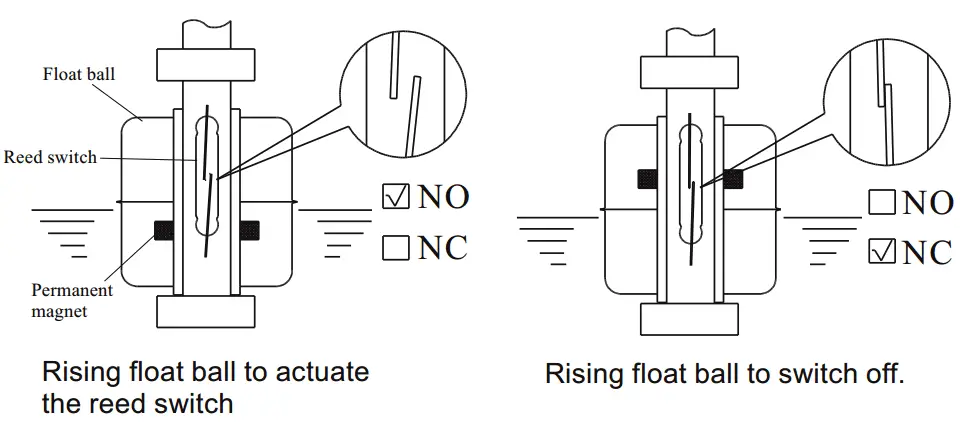
The single unit or multiple reed switch units are housed tightly in stainless steel or engineering plastic stem, and the permanent magnet is sealed into the middle of the specified float ball(s). You can mount the float ball to penetrating through the stem, then the liquid buoyancy will deliver the float ball up and down at the specified position by graduating rings.

When the float internal magnet approaches the reed switch, it will actuate the reed switch contact point to create an open or close circuit. We can apply such on-off output signals to reach liquid level controlling and monitoring purpose. The figures below show the float orientations on N.O. (Normal Open) and N.C. (Normal Close).

Also See : Magnetic Float Level Switch Animation

Magnetic Float Level Switch Principle

Installation Techniques

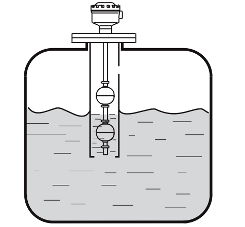
The float level switch should be mounted far away from liquid inlet. Any strong liquid fluctuation will produce error output signals.

Magnetic Float Level Switch Installation Techniques

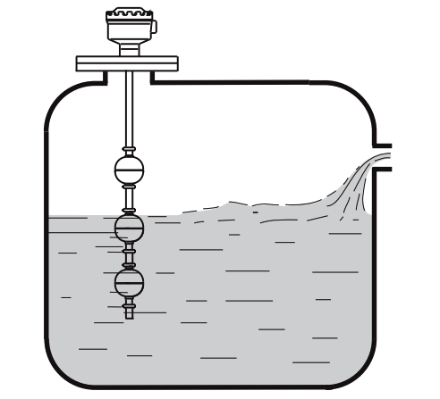
It is advised to place a pipe shield or equivalent device to normalize the switch actuation if the switch is used near agitator.

Magnetic Float Level Switch Installation Techniques 2

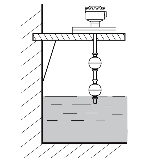
It had better require an L type supporter, when the switch is mounted in concrete wall tank as figure below.

Magnetic Float Level Switch Installation Techniques 3It is recommended to select the standpipe with diameter larger than the float ball for installation process.
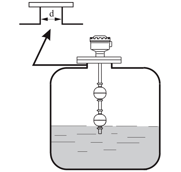
Magnetic Float Level Switch Installation Techniques 4

Source : FineTek

Don't Miss Our Updates
Be the first to get exclusive content straight to your email.
We promise not to spam you. You can unsubscribe at any time.
Invalid email address
You've successfully subscribed !

Continue Reading

How Not to Install an Instrument and Wrong Practices
Important Factors Consider during Piping Design
What are the Mounting Techniques of Diaphragm Seals?
Field Instruments Mounting brackets
Control Valves Pre-Commissioning Checklist
Importance of Magnetic Flow Meters Grounding
Share This Article
Facebook Whatsapp Whatsapp LinkedIn Copy Link
Share
Leave a Comment

Leave a Reply Cancel reply

Your email address will not be published. Required fields are marked *

Stay Connected

128.3kFollowersLike
69.1kFollowersFollow
210kSubscribersSubscribe
38kFollowersFollow

Categories

Explore More

Pressure Transmitter Heated Enclosures
Instrument Tube Fitting Installation – Part 2
Selection Guidelines for Cable Glands
Material Certificate versus Positive Material Identification (PMI)
Instrument Tube Fitting Installation – Part 3
Installation Precautions of Thermocouple and RTD
Turbine Flow Meter Installation Procedure
Good and Bad Wiring Practices

Keep Learning

P&ID Guidelines for Pumps

P&ID Guidelines for Pumps

What is FAT and SAT?

What is FAT and SAT? Difference between them

Pipeline Project Management

Pipeline Project Management

How to Solve Cable Tray Sagging

How to Solve Cable Tray Sagging ?

Installation and Maintenance of Control Valves

Installation and Maintenance of Control Valves

Hook-up Diagram for Pressure Gauge

What is Instrument Hook Up Diagram ?

Gas Detectors Location Installation

Gas Detectors Installation Techniques

cable-trays-glossary

Cable Trays Glossary

Learn More

How to test SCR using Multimeter

How to test SCR using Multimeter

PLC Battery

Everything You Need to Know About PLC Battery

PLC Best Practices

#1 PLC Best Practices – Split PLC Code into Modules

How to Design a Motor Faceplate in Graphics - SCADA Tutorials

How to Design a Motor Faceplate in Graphics? – SCADA Tutorials

Digital Control Systems

The Z-Transform

Modbus Vs DNP3

Difference between Modbus and DNP3 Communication Protocols

Difference Between Microcontroller and Microprocessor

Difference Between Microcontroller and Microprocessor

DP-Flow-Transmitter-Re-Ranging-calculation

DP Flow Transmitter Re-Ranging Calculation

Menu

  • About
  • Privacy Policy
  • Copyright

Quick Links

  • Learn PLC
  • Helping Hand
  • Part Time Job

YouTube Subscribe

Follow US
All rights reserved. Reproduction in whole or in part without written permission is prohibited.
Welcome Back!

Sign in to your account

Username or Email Address
Password

Lost your password?