Inst ToolsInst ToolsInst Tools
  • Courses
  • Automation
    • PLC
    • Control System
    • Safety System
    • Communication
    • Fire & Gas System
  • Instrumentation
    • Design
    • Pressure
    • Temperature
    • Flow
    • Level
    • Vibration
    • Analyzer
    • Control Valve
    • Switch
    • Calibration
    • Erection & Commissioning
  • Interview
    • Instrumentation
    • Electrical
    • Electronics
    • Practical
  • Q&A
    • Instrumentation
    • Control System
    • Electrical
    • Electronics
    • Analog Electronics
    • Digital Electronics
    • Power Electronics
    • Microprocessor
  • Request
Search
  • Books
  • Software
  • Projects
  • Process
  • Tools
  • Basics
  • Formula
  • Power Plant
  • Root Cause Analysis
  • Electrical Basics
  • Animation
  • Standards
  • 4-20 mA Course
  • Siemens PLC Course
Reading: Low Voltage Protection (LVP) and Low Voltage Release (LVR)
Share
Font ResizerAa
Inst ToolsInst Tools
Font ResizerAa
  • Courses
  • Design
  • PLC
  • Interview
  • Control System
Search
  • Courses
  • Automation
    • PLC
    • Control System
    • Safety System
    • Communication
    • Fire & Gas System
  • Instrumentation
    • Design
    • Pressure
    • Temperature
    • Flow
    • Level
    • Vibration
    • Analyzer
    • Control Valve
    • Switch
    • Calibration
    • Erection & Commissioning
  • Interview
    • Instrumentation
    • Electrical
    • Electronics
    • Practical
  • Q&A
    • Instrumentation
    • Control System
    • Electrical
    • Electronics
    • Analog Electronics
    • Digital Electronics
    • Power Electronics
    • Microprocessor
  • Request
Follow US
All rights reserved. Reproduction in whole or in part without written permission is prohibited.
Inst Tools > Blog > Electrical Theory > Low Voltage Protection (LVP) and Low Voltage Release (LVR)

Low Voltage Protection (LVP) and Low Voltage Release (LVR)

Last updated: August 17, 2018 1:34 pm
Editorial Staff
Electrical Theory
No Comments
Share
3 Min Read
SHARE

Within the two basic categories of motor controllers, there are three major types of AC acrossthe-line controllers in use today. There are low-voltage protection (LVP), low-voltage release (LVR), and low-voltage release effect (LVRE) controllers.

The main purpose of an LVP controller is to de-energize the motor in a low voltage condition and keep it from re-starting automatically upon return of normal voltage (Below Figure).

LVP Controller Operation:

LVP Motor Controller Principle

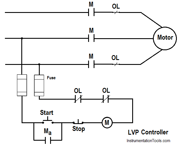
Figure : LVP Controller


  1. Push the START button, which energizes contactor coil M, closing the M and Ma contacts. When the START button is released, the circuit will remain complete, because the Ma contact remains closed, shunting the open start switch.
  2. When a low voltage condition occurs, the M coil will drop out at some pre-determined value of voltage, and the M and Ma contacts will open. The START button must then be pushed to restart the motor.
  3.  Depressing the STOP button deenergizes the M coil, which then opens the M and Ma contacts.

The purpose of the LVR controller is to de-energize the motor in a low voltage condition and restart the motor when normal voltage is restored. This type of controller (Below Figure) is used primarily on small and/or critical loads (e.g., cooling water pumps required for safety-related equipment).

LVR Controller Operation:

LVR Motor Controller Operation

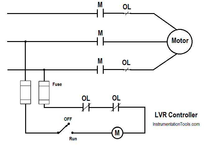
Figure : LVR Controller

  1. Place the START switch in Run which energizes coil M, closing the M contacts and starting the motor.
  2. When a low voltage condition occurs, the M coil drops out, opening the M contacts and de-energizing the motor. When normal voltage is restored, the M coil is again energized, closing the M contacts and restarting the motor.

The LVRE controller maintains the motor across the line at all times. This type of controller is of the manual variety and is found mostly on small loads that must start automatically upon restoration of voltage (Below Figure). An LVRE controller may or may not contain overloads. If overloads are used, they will be placed in the lines to the load.

LVRE Motor controller

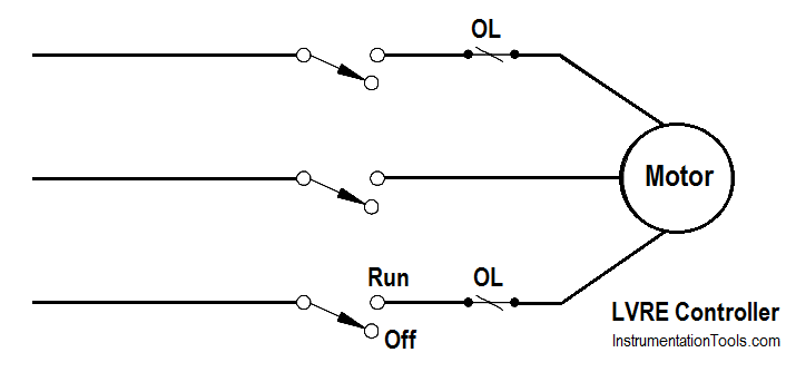
Figure : LVRE Controller

The motor controllers that have been discussed are very basic. There are many automatic control functions that can be incorporated into these types of controllers.

Don't Miss Our Updates
Be the first to get exclusive content straight to your email.
We promise not to spam you. You can unsubscribe at any time.
Invalid email address
You've successfully subscribed !

Continue Reading

Schematic Diagram
What is Synchroscope ?
Unbalanced 3 Phase Loads
Methods of Producing Voltage (Electricity)
Transformer Efficiency
Half-Wave Rectifier Circuit
Share This Article
Facebook Whatsapp Whatsapp LinkedIn Copy Link
Share
Leave a Comment

Leave a Reply Cancel reply

Your email address will not be published. Required fields are marked *

Stay Connected

128.3kFollowersLike
69.1kFollowersFollow
210kSubscribersSubscribe
38kFollowersFollow

Categories

Explore More

Full-Wave Rectifier Circuit
Current Division
What is Electricity ?
Impedance
4-Wire, Three-Phase Delta Wiring System
Transformer Current Ratio
DC Circuit Analysis Loop Equations
Single Phase Power Wiring Schemes

Keep Learning

3-Wire, Three-Phase Delta Wiring System

3-Wire, Three-Phase Delta Wiring System

Types of Capacitors

Types of Capacitors

Starting a Synchronous Motor

Starting a Synchronous Motor

AC Generator Operation

AC Generator Theory

Transformer voltage and turns ratio

Transformer Voltage Ratio

Three Phase AC Generators

Three Phase AC Generators

AC Generator Operation

Losses in AC Generator

Three Phase Wattmeter principle

Ampere Hour Meter

Learn More

Siemens PCS 7

What is PCS 7?

Yokogawa differential pressure transmitter

Basics of Differential Pressure Transmitters

Artificial intelligence in supply chain management

The Role of AI in Supply Chain Management – Examples & Benefits

Kiln

Kiln Inlet Gas Analyzer

What is a Bus Coupler in Electrical Panel

What is a Bus Coupler in Electrical Panel?

thermocouple voltages

Manually Interpreting Thermocouple Voltages

Density Measurement Objective Questions

Density Measurement Objective Questions

plc-analog-signals-wiring-techniques

PLC Analog Signals Wiring Techniques

Menu

  • About
  • Privacy Policy
  • Copyright

Quick Links

  • Learn PLC
  • Helping Hand
  • Part Time Job

YouTube Subscribe

Follow US
All rights reserved. Reproduction in whole or in part without written permission is prohibited.
Welcome Back!

Sign in to your account

Username or Email Address
Password

Lost your password?