Two rotating impellers, designed with a figure eight cross-section, rotate in opposite directions due to the forces exerted by the gas flow being measured.
The shape of the impellers prevents contact while the gap between them remains constant.
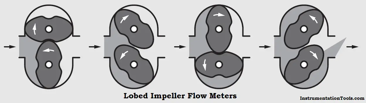
A gear drive external to the measuring chamber synchronizes the impellers. During each rotation, four crescent-shaped volumes are moved through the measuring chamber. The number of rotations is proportional to the flow. The rotation is coupled using an adjustable fine-tooth gear train to the totalizer.
An unmeasured flow, which is a function of the pressure drop, flows through the gaps. The negative error is compensated by an adjustment. The viscosity of flow increases at high pressures and reduces the losses in the gaps which compensates for the higher losses which would otherwise exist due to the higher pressure difference.
The pulsations in the flow discharge can cause the pipe system connected to the meter to vibrate. If resonance should occur, loud noises and sudden pressure drops can result. This condition should not be allowed to occur; if necessary noise or pulsation dampers should be utilized.
The pressure drop results from the mechanical and dynamic resistances in the meter. The dynamic portion increases appreciably with increasing load.
Lobed impeller meters are very susceptible to contamination. Since contamination affects the pressure drop it must be monitored and the meter cleaned when required.
If you liked this article, then please subscribe to our YouTube Channel for Instrumentation, Electrical, PLC, and SCADA video tutorials.
You can also follow us on Facebook and Twitter to receive daily updates.
Read Next:
Learn the example of flip-flop PLC program for lamps application using the ladder logic to…
In this article, you will learn the STAR DELTA programming using PLC controller to start…
Lube oil consoles of rotary equipment packages in industrial process plants are usually equipped with…
Rotating equipment packages such as pumps, compressors, turbines need the lube oil consoles for their…
This article explains how to blink lights in ladder logic with a detailed explanation video…
In this article, a simple example will teach you the conversion from Boolean algebra to…

