Inst ToolsInst ToolsInst Tools
  • Courses
  • Automation
    • PLC
    • Control System
    • Safety System
    • Communication
    • Fire & Gas System
  • Instrumentation
    • Design
    • Pressure
    • Temperature
    • Flow
    • Level
    • Vibration
    • Analyzer
    • Control Valve
    • Switch
    • Calibration
    • Erection & Commissioning
  • Interview
    • Instrumentation
    • Electrical
    • Electronics
    • Practical
  • Q&A
    • Instrumentation
    • Control System
    • Electrical
    • Electronics
    • Analog Electronics
    • Digital Electronics
    • Power Electronics
    • Microprocessor
  • Request
Search
  • Books
  • Software
  • Projects
  • Process
  • Tools
  • Basics
  • Formula
  • Power Plant
  • Root Cause Analysis
  • Electrical Basics
  • Animation
  • Standards
  • 4-20 mA Course
  • Siemens PLC Course
Reading: Why have been limits imposed on the frequency ratio for thermowells?
Share
Font ResizerAa
Inst ToolsInst Tools
Font ResizerAa
  • Courses
  • Design
  • PLC
  • Interview
  • Control System
Search
  • Courses
  • Automation
    • PLC
    • Control System
    • Safety System
    • Communication
    • Fire & Gas System
  • Instrumentation
    • Design
    • Pressure
    • Temperature
    • Flow
    • Level
    • Vibration
    • Analyzer
    • Control Valve
    • Switch
    • Calibration
    • Erection & Commissioning
  • Interview
    • Instrumentation
    • Electrical
    • Electronics
    • Practical
  • Q&A
    • Instrumentation
    • Control System
    • Electrical
    • Electronics
    • Analog Electronics
    • Digital Electronics
    • Power Electronics
    • Microprocessor
  • Request
Follow US
All rights reserved. Reproduction in whole or in part without written permission is prohibited.
Inst Tools > Blog > Temperature Measurement > Why have been limits imposed on the frequency ratio for thermowells?

Why have been limits imposed on the frequency ratio for thermowells?

Last updated: October 31, 2019 9:48 am
Editorial Staff
Temperature Measurement
No Comments
Share
4 Min Read
SHARE

In 1995, an accident caused due to breaking thermowells in Monju Nuclear Plant reactor, led to very serious damages to the surrounding facilities.

Thermowells located on a line carrying liquid sodium coolant were subjected to intense vibration and eventually broken.

As a result 3 tons of sodium coolant leaked out of the pipes. When contacted with the air, the liquid sodium spontaneously reacted with oxygen and moisture in the air, filling the room with sodium fumes and producing temperature of several hundred degrees Celsius. Intense heat generated damaged several steel structures in the room.

The investigations after the accident pointed towards the thermowell damage being the root cause and this accident led to the development of Performance Test Codes (PTC) 19.3 (2010) to be followed by the thermowell manufacturers.

These codes impose maximum limitations on the vibration frequencies for the thermowells.Thermowell Frequency Ratio - 2

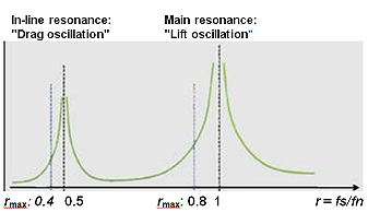
ASME PTC 19.3 TW-2010 is divided into dynamic and static calculation results. For gaseous media, the previous limit frequency, r max = 0.8, from PTC 19.3-1974, is still valid.

For liquid media, in many applications, the newly-introduced limit frequency of r max = 0.4, applicable for the inline resonance. The evaluation of the dynamic results is made using the damping factor NSC.

For gaseous media, a characteristic value is NSC > 2.5; fluids typically have an NSC < 2.5.

Whether frequency ratio r < 0.8, can also be used as an evaluation limit with liquid process media, is determined through a consideration of the permissible stresses in the thermowell material with respect to the actual stresses at resonance.

In addition, an evaluation of the strength of thermowell material with respect to flexural fatigue stress in area of thermowell clamping is carried out.

The results of static analysis as per ASME PTC 19.3 TW-2010 are generated from the maximum permissible process pressure (dependent upon the process temperature and the geometry of the thermowell) and the bending stress in the area of thermowell root.

Bending stresses are caused by the incident flow on the thermowell, and is dependent on the shielded length of the flange adapter.

For fabricated thermowells, the calculation method per Dittrich/Klotter must be used because this construction is not covered by ASME PTC 19.3 TW-2010.The approach is based on calculating the stresses occurring under load.

These are compared with allowable stresses for the thermowell and safety factors.

Remedies using structural changes, when r max (permissible), is exceeded

By exceeding the maximum permissible limit frequency, r max, for the “In-line”- or main resonance, following structural changes should be made:Thermowell Frequency Ratio

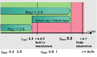
a) Shortening of insertion length

This is the most effective method (and the recommended method from ASME PTC 19.3 TW-2010) for improvement of frequency ratio r.

b) Increasing the tip diameter

By the enlargement of the tip diameter, natural frequency fs is reduced, as well as the frequency ratio r is optimized.

c) Support through an anchor

Support of the thermowell through an anchor is generally not recommended by ASME PTC 19.3 TW-2010, and lies outside the scope of the ASME code.

On customer request, an anchor can be used, in line with precise customer specifications and the process side thermowell components below the anchor connection will be designed in accordance with the design and calculation criteria of ASME PTC 19.3 TW-2010, without, however, falling within the scope of ASME PTC 19.3 TW-2010.

The operator is responsible for the rigid support of the anchor in the adapter, which may mean that a reworking of the adapter is needed.

Don't Miss Our Updates
Be the first to get exclusive content straight to your email.
We promise not to spam you. You can unsubscribe at any time.
Invalid email address
You've successfully subscribed !

Continue Reading

Interview Questions on Temperature Measurement
Resistance Temperature Detectors (RTD) Construction
Temperature Error of 2-Wire, 3-Wire & 4-Wire RTD
Use of Temperature Transmitters instead of Direct Wiring
Thermowell Insertion and Immersion Length
Thermal Imaging Temperature Measurement
Share This Article
Facebook Whatsapp Whatsapp LinkedIn Copy Link
Share
Leave a Comment

Leave a Reply Cancel reply

Your email address will not be published. Required fields are marked *

Stay Connected

128.3kFollowersLike
69.1kFollowersFollow
210kSubscribersSubscribe
38kFollowersFollow

Categories

Explore More

What is Temperature ?
What is a Three-wire RTD ?
Pyrometers Handbook
Thermowell Outer Diameter Larger than Nozzle Inside Diameter?
Calculate Temperature Coefficient of RTD
Thermocouples Burnout detection
Applications of Temperature Scanner
Difficulties with Thermocouples for Temperature Measurement

Keep Learning

Filled-bulb Temperature Measurement

Filled-bulb Temperature Sensors

Thermocouple Calculations

Thermocouple Calculations

Laws of Thermocouples

Thermowell Installation near Critical Equipment

Thermowell Installation near Critical Equipment

thermocouple head

Thermocouples Connector and Tip styles

Comparison of Temperature Sensors - Industrial Process Control

Comparison of Temperature Sensors – Industrial Process Control

How to Select Right Thermocouple and Thermowell

How to Select Right Thermocouple & Thermowell ?

Thermocouple Law of Intermediate Metals

Thermocouples Law of Intermediate Metals

Learn More

How to Update the Firmware Version of your PLC

How to Update the Firmware Version of your PLC? – TIA Portal

Remote Seal Pressure Transmitter Temperature

Importance of Temperature in Remote Seal Pressure Transmitter

Safety PLC System

SIS Maintenance – Safety Instrumented System

Turbine Flow Meter (TFM) Field Calibration

Turbine Flow Meter (TFM) Field Calibration Uncommon Request

PLC DIN Rail

What is DIN rail ?

Power System Interview Question and Answers

Power System Interview Question and Answers

Ultrasonic Flowmeters Principle

Factors Affecting the Performance of Ultrasonic Flow Meters

Electrical Machines Objective Questions

Electrical Machines MCQ Series 16

Menu

  • About
  • Privacy Policy
  • Copyright

Quick Links

  • Learn PLC
  • Helping Hand
  • Part Time Job

YouTube Subscribe

Follow US
All rights reserved. Reproduction in whole or in part without written permission is prohibited.
Welcome Back!

Sign in to your account

Username or Email Address
Password

Lost your password?