Another category of control strategies involves the use of signal relays or function blocks with the ability to switch between different signal values, or re-direct signals to new pathways.
Such functions are useful when we need a control system to choose between multiple signals of differing value in order to make the best control decisions.
The “building blocks” of such control strategies are special relays (or function blocks in a digital control system) shown here:
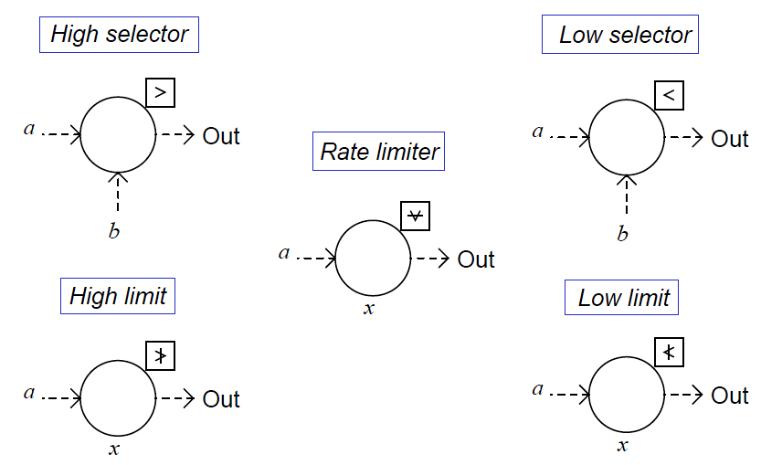
High-select functions output whichever input signal has the greatest value. Low-select functions do just the opposite: output whichever input signal has the least value.
“Greater-than” and “Less than” symbols mark these two selector functions, respectively, and each type may be equipped to receive more than two input signals.
Sometimes you will see these relays represented in P&IDs simply by an inequality sign in the middle of the large bubble, rather than off to the side in a square.
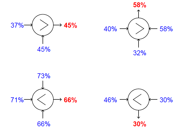
You should bear in mind that the location of the input lines has no relationship at all to the direction of the inequality symbol – e.g., it is not as though a high-select relay looks for the input on the left side to be greater than the input on the right.
Note the examples shown below, complete with sample signal values:
High-limit and low-limit functions are similar to high- and low-select functions, but they only receive one input each, and the limit value is a parameter programmed into the function rather than received from another source.
The purpose of these functions is to place a set limit on how high or how low a signal value is allowed to go before being passed on to another portion of the control system.
If the signal value lies within the limit imposed by the function, the input signal value is simply passed on to the output with no modification.
Like the select functions, limit functions may appear in diagrams with nothing more than the limit symbol inside the bubble, rather than being drawn in a box off to the side:
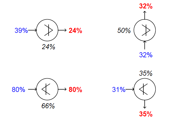
Rate limit functions place a maximum rate-of-change limit on the input signal, such that the output signal will follow the input signal precisely until and unless the input signal’s rate-of-change over time ( dx/dt ) exceeds the pre-configured limit value.
In that case, the relay still produces a ramping output value, but the rate of that ramp remains fixed at the limit dx/dt value no matter how fast the input keeps changing.
After the output value “catches up” with the input value, the function once again will output a value precisely matching the input unless the input begins to rise or fall at too fast a rate again.
Also Read : Limit Controls : High Limit & Low Limit Functions


Dear Sir
i need a Fisher Valve CASCADE CONTROL