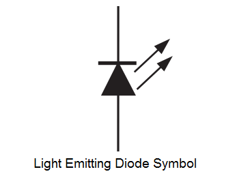
The symbol for an LED is shown in Figure.
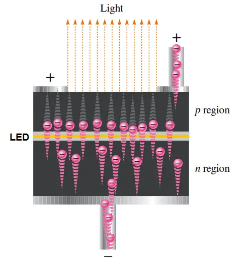
The basic operation of the light-emitting diode (LED) is as follows. When the device is forward-biased, electrons cross the pn junction from the n-type material and recombine with holes in the p-type material. Recall from Chapter 1 that these free electrons are in the conduction band and at a higher energy than the holes in the valence band. The difference in energy between the electrons and the holes corresponds to the energy of visible light. When recombination takes place, the recombining electrons release energy in the form of photons.
The emitted light tends to be monochromatic (one color) that depends on the band gap (and other factors). A large exposed surface area on one layer of the semiconductive material permits the photons to be emitted as visible light. This process, called electroluminescence, is illustrated in Figure 3–29. Various impurities are added during the doping process to establish the wavelength of the emitted light. The wavelength determines the color of visible light. Some LEDs emit photons that are not part of the visible spectrum but have longer wavelengths and are in the infrared (IR) portion of the spectrum.
Light Emitting Diodes (LED) Materials
An important class of commercial LEDs that cover the visible spectrum are the III-V. ternary alloys based on alloying GaAs and GaP which are denoted by GaAs1-yPy. InGaAlP is an example of a quarternary (four element) III-V alloy with a direct band gap.
The LEDs realized using two differently doped semiconductors that are the same material is called a homojunction. When they are realized using different bandgap materials they are called a heterostructure device. A heterostructure LED is brighter than a homo Junction LED.
Light Emitting Diodes (LED) Structure
The LED structure plays a crucial role in emitting light from the LED surface. The LEDs are structured to ensure most of the recombinations takes place on the surface by the following two ways.
- By increasing the doping concentration of the substrate, so that additional free minority charge carriers electrons move to the top, recombine and emit light at the surface.
- By increasing the diffusion length L = √ Dτ, where D is the diffusion coefficient and τ is the carrier life time. But when increased beyond a critical length there is a chance of re-absorption of the photons into the device.
The LED has to be structured so that the photons generated from the device are emitted without being reabsorbed. One solution is to make the p layer on the top thin, enough to create a depletion layer. Following picture shows the layered structure. There are different ways to structure the dome for efficient emitting.
Light Emitting Diodes (LED) Structure
LEDs are usually built on an n-type substrate, with an electrode attached to the p-type layer deposited on its surface. P-type substrates, while less common, occur as well. Many commercial LEDs, especially GaN/InGaN, also use sapphire substrate.
Light Emitting Diodes (LED) Efficiency
A very important metric of an LED is the external quantum efficiency ηext. It quantifies the efficeincy of the conversion of electrical energy into emitted optical energy. It is defined as the light output divided by the electrical input power. It is also defined as the product of Internal radiative efficiency and Extraction efficiency.
ηext = Pout(optical) / IV
For indirect bandgap semiconductors ηext is generally less than 1%, where as for a direct band gap material it could be substantial.
ηint = rate of radiation recombination/ Total recombination
The internal efficiency is a function of the quality of the material and the structure and composition of the layer.
Light Emitting Diodes (LED) Application
LED have a lot of applications. Following are few examples.
- Devices, medical applications, clothing, toys
- Remote Controls (TVs, VCRs)
- Lighting
- Indicators and signs
- Optoisolators and optocouplers
Advantages Of Using Light Emitting Diodes (LED)
- LEDs produce more light per watt than incandescent bulbs; this is useful in battery powered or energy-saving devices.
- LEDs can emit light of an intended color without the use of color filters that traditional lighting methods require. This is more efficient and can lower initial costs.
- The solid package of the LED can be designed to focus its light. Incandescent and fluorescent sources often require an external reflector to collect light and direct it in a usable manner.
- When used in applications where dimming is required, LEDs do not change their color tint as the current passing through them is lowered, unlike incandescent lamps, which turn yellow.
- LEDs are ideal for use in applications that are subject to frequent on-off cycling, unlike fluorescent lamps that burn out more quickly when cycled frequently, or High Intensity Discharge (HID) lamps that require a long time before restarting.
- LEDs, being solid state components, are difficult to damage with external shock. Fluorescent and incandescent bulbs are easily broken if dropped on the ground.
- LEDs can have a relatively long useful life. A Philips LUXEON k2 LED has a life time of about 50,000 hours, whereas Fluorescent tubes typically are rated at about 30,000 hours, and incandescent light bulbs at 1,000–2,000 hours.
- LEDs mostly fail by dimming over time, rather than the abrupt burn-out of incandescent bulbs.
- LEDs light up very quickly. A typical red indicator LED will achieve full brightness in microseconds; Philips Lumileds technical datasheet DS23 for the Luxeon Star states “less than 100ns.” LEDs used in communications devices can have even faster response times.
- LEDs can be very small and are easily populated onto printed circuit boards.
- LEDs do not contain mercury, unlike compact fluorescent lamps.
Disadvantages Of Light Emitting Diodes (LED)
- LEDs are currently more expensive, price per lumen, on an initial capital cost basis, than more conventional lighting technologies. The additional expense partially stems from the relatively low lumen output and the drive circuitry and power supplies needed. However, when considering the total cost of ownership (including energy and maintenance costs), LEDs far surpass incandescent or halogen sources and begin to threaten the future existence of compact fluorescent lamps.
- LED performance largely depends on the ambient temperature of the operating environment. Over-driving the LED in high ambient temperatures may result in overheating of the LED package, eventually leading to device failure. Adequate heat-sinking is required to maintain long life.
- LEDs must be supplied with the correct current. This can involve series resistors or current-regulated power supplies.
- LEDs do not approximate a “point source” of light, so they cannot be used in applications needing a highly collimated beam. LEDs are not capable of providing divergence below a few degrees. This is contrasted with commercial ruby lasers with divergences of 0.2 degrees or less. However this can be corrected by using lenses and other optical devices.
- There is increasing concern that blue LEDs and white LEDs are now capable of exceeding safe limits of the so-called blue-light hazard as defined in the eye safety specifications for example ANSI/IESNA RP-27.1-05: Recommended Practice for Photobiological Safety for Lamp and Lamp Systems.
Light emitting diodes (LED) in the future have come a long way and currently they are widely used in many applications.


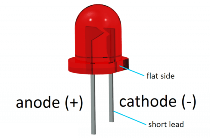
Be aware that your figure of Light Emitting Diodes (LED) Structure in this article is wrong. The cathode and anode inside the LED house are switched. The “big” metal part is the cathode and the “small” is the anode.
Yes, even if I realize it suddenly, but for the people who don’t know before, will be frustating. We must see the inside of LED, not the foot of LED