In this article, we will learn a ladder logic example of two motors interlinked with another motor.
In this post, we will study a case of ladder logic. There are two motors – motor A & motor B. And third motor – C is interlinked with both these motors.
There will be a selection for running the two motors of A & B either simultaneously or individually.
If either the motors (A/B) or a single motor is running depending upon the selection, then the third motor will run.
If any single motor is off, then the third motor too will remain off.
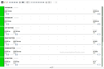
Ladder Logic Example of Two Motors
Let us have a look at the ladder logic for the same accordingly.
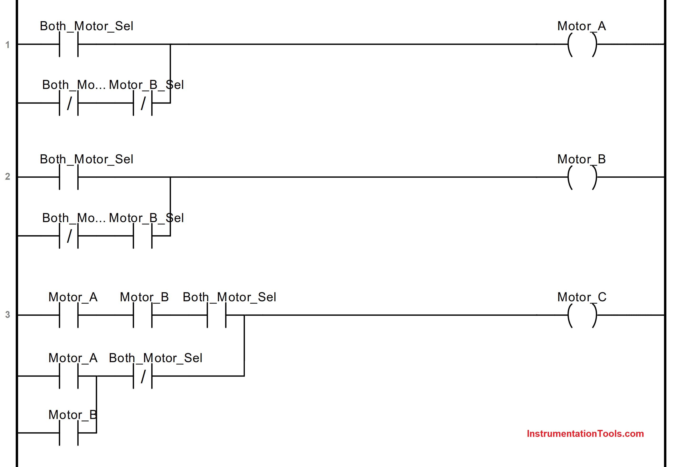
Refer to the below image for the logic written. Let us understand each rung one by one.
First Rung
The first rung is used to turn on or off the first motor – A. If both the motors are selected to be running, then this motor will run.
If only a single motor is selected to be running, then depending upon the motor selection, this motor will operate.
In this case, the selection input must be off for turning on the output.
Second Rung
The second rung is used to turn on or off the second motor – B. If both the motors are selected to be running, then this motor will run.
If only a single motor is selected to be running, then depending upon the motor selection, this motor will operate.
In this case, the selection input must be on for turning on the output.
Third Rung
The third rung is used to turn on or off the third motor – C. If both the motors are selected to be running, then this motor will run only when both the previous motors are running.
If only a single motor is selected to be running, then this motor will run if either of the output is running.
In this way, we had a case study of the following example in ladder logic.
If you liked this article, then please subscribe to our YouTube Channel for Electrical, Electronics, Instrumentation, PLC, and SCADA video tutorials.
You can also follow us on Facebook and Twitter to receive daily updates.
Read Next:
- Ladder Logic Example
- WinCC Runtime Advanced
- Why 24 Volts DC Power Supply?
- Communication in S7-1200 PLC
- Factory Acceptance Test of PLC