In this article, you will learn the PLC ladder diagram example using memory bits and set coils to control the motors.
Note: The ladder diagram example is for students and fresh engineering graduates.
Memory Bits and Set Coils
Problem Statement
Design a PLC ladder logic for the following application.
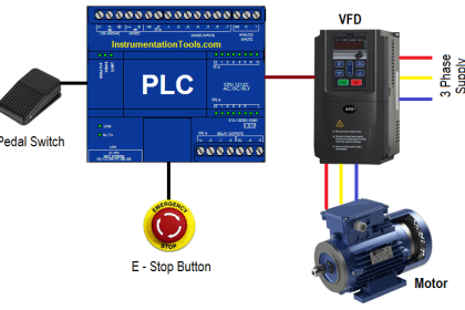
We are using one toggle switch to control four motors.
If Switch 1 is ON, then Motor I, Motor II, Motor III, and Motor IV will be ON.
If Switch 1 is OFF, then Motor I and Motor II, Motor III, and Motor IV remain ON.
PLC Training Video
Watch this video to understand the given example program with a step-by-step approach.
Inputs in PLC
The inputs of this PLC program are given below.
Switch 1: I0.0
Memory bit: M1
Outputs in PLC
The outputs of this PLC program are given below.
Motor 1: Q0.0
Motor 2: Q0.1
Motor 3: Q0.2
Motor 4: Q0.3
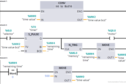
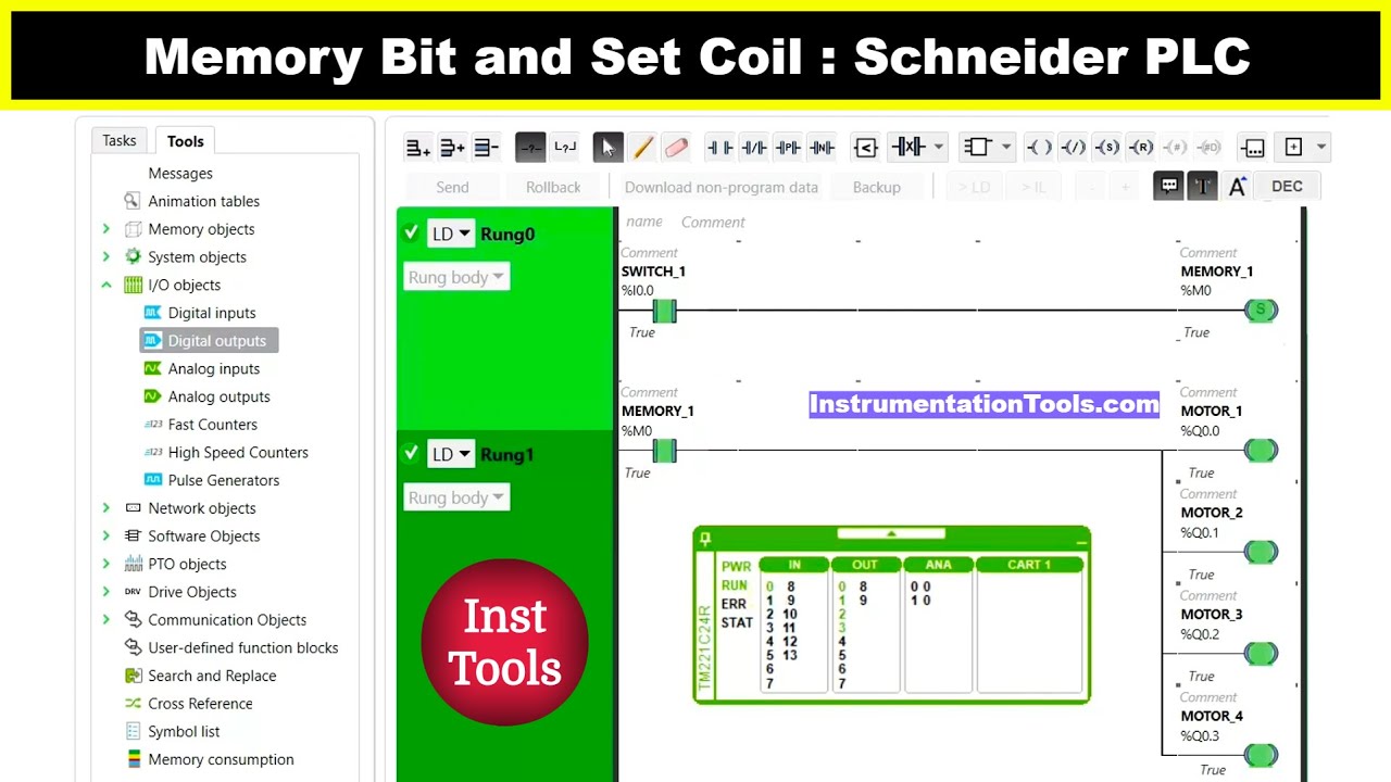
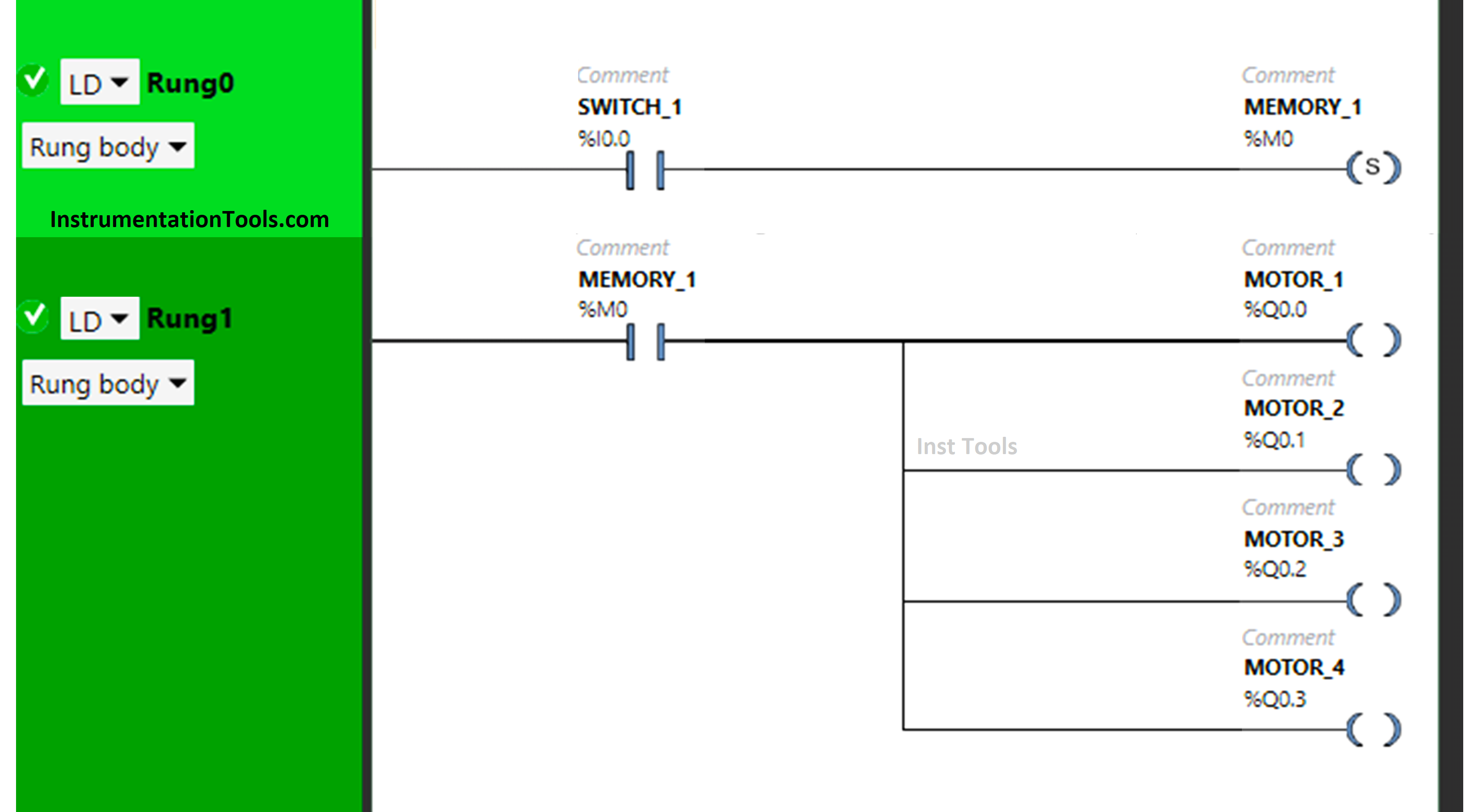
Ladder Diagram for Motors
Program Explained
In this program, we used the Schneider Electric PLC software.
In the above program, we have used Normally Open Contact for Switch 1 (I0.0).
We have also used a set coil for the Memory bit (M0).
In Rung1, switch 1 is connected with a set coil for the Memory Bit.
Motor 1, Motor 2, Motor 3, and Motor 4 are connected to the input Memory Bit present in Rung1.
For Motor 1, Motor 2, Motor 3, and MOTOR 4 to turn ON, input Switch 1 should be ON.
All Motors will remain ON if switch 1 is turned OFF as switch 1 is connected with a set coil representing the memory bit.
PLC Result
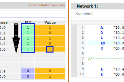
When Switch 1 is ON
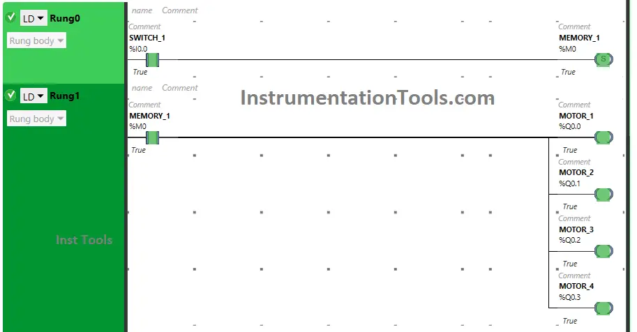
In Rung 0, there is use of Set Coil for Memory Bit and switch 1 is used as Normally Open Contact. When switch 1 is turned ON, it will allow signal to flow through it and it will make the memory bit true
Then in Rung 1, Motor 1, Motor 2, Motor 3 and Motor 4 connected to the Memory Bit will turn ON.
When Switch 1 is OFF
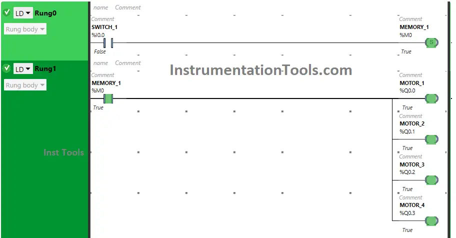
In Rung 0, Memory Bit remains true even when the input switch 1 is turned OFF.
It is so because the set coil used sets itself true when the input gets ON and retains its true state even when its input is turned OFF. Then in Rung 1, Memory Bit which is still true will keep Motor 1, Motor 2, Motor 3, and Motor 4 ON.
If you liked this article, please subscribe to our YouTube Channel for PLC and SCADA video tutorials.
You can also follow us on Facebook and Twitter to receive daily updates.
Read Next:
- PLC Program for Stage Control Task
- How to Get a PLC Programmer Job?
- Advanced PLC Conveyor Control Program
- PLC Based Product Sorting Machine
- Sorting Example PLC Programming