Intrinsic safety of instruments will not release enough electrical or thermal energy under normal operating conditions to ignite a specific flammable or combustible atmospheric mixture in its ignitable concentration.
Unusual conditions may include accidental damage to any field-installed wiring, damage to electrical components, application of over-voltage, adjustment and maintenance operations, and other similar conditions. A combustible mixture is heated to its ignition temperature for the explosion.
Intrinsic Safety of Instruments
A weak spark heats the little amount of mixture that heat loss exceeds the heat supply and the initial explosion dies out. A large spark heats enough mixture for combustion to sustain itself and an explosion gets propagated. Ignition doesn’t occur for low-level energy. This is called intrinsic safety.
For normal operation, it is not sufficient if energy is less. It should be below under any possible abnormal operation or fault condition.
Energy Levels
Defining safe energy levels in the easiest way cannot be done. Ignition is based on specific gas, gas concentration, voltage, current, energy storage elements, contact materials, contact size, and speed of opening and closing of contacts.
Actual ignition testing of the specific apparatus is most preferred in practice.
Loop Concept
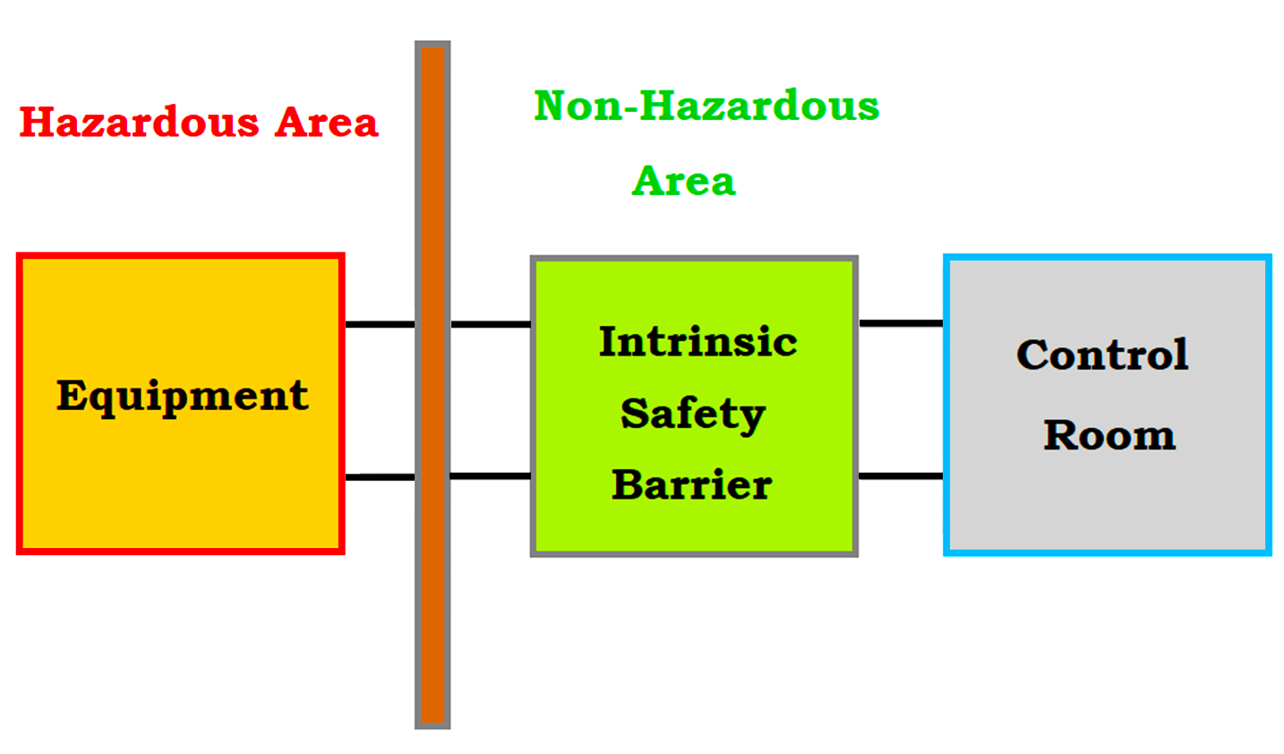
In estimating an instrument for its intrinsic safety, it is essential to look at all elements of the complete loop.
For example, an ordinary thermocouple is safe. The addition of a simple millivolt indicator ensures more safety. Link the thermocouple to a recorder powered by a 220 V AC line power supply.
Something recorder error may put hazardous energy on the thermocouple leads. This error can be solved easily by good design and construction of the recorder. Anybody should estimate the combination of the loop elements and assume responsibility for safety.
Determining Intrinsic Safety
The instrument buyer and user must check the certificate provided by a qualified testing agency.
While each testing agency has individual detailed rules and traditions.
Typical evaluation involves three basic steps
- Circuit analysis in determining trash fault conditions.
- Estimation to assure safety margin conditions.
- Construction assures that dangerous components are reliable, and the circuit works accordingly as per plan.
Circuit Analysis
It is an assessment of the circuit component by considering the possible failure mode of each and its effects on available energy levels in the hazardous area.
It initializes at the entry of system line power and includes all parts of the inter-connected instrument system such as the control room located or field located.
The object is to spot the fault condition or combination of conditions that allow the highest energy in the field circuits.
Evaluation
The purpose is to discover if each fault condition accounts for the possibility of ignition. By using actual circuits, these faults are generated by short-circuiting or open-circuiting components with the field leads linked to a test apparatus.
The test apparatus includes a pair of contacts working in a chamber filled with the immediate igniting mixtures of a suitable combustible gas with oxygen. The contacts replicate a broken cable, a wire hauling on a surface, or short-circuiting of leas pairs.
It is also desirable to use measured voltages, currents, inductances, capacitances, etc., and compare them with previous test results of similar circuit parameters.
Construction Review
A circuit element should be of good construction form if it depends upon safety. A transformer that resists a high potential immediately after burning intentionally is considered reliable. This requires that the transformer is constructed so that an appropriate performance of this nature can be predicted.
A resistor must resist total overload without significant change in its value. Live parts such as terminals must be isolated to avoid possible accidental short-circuit. Its safety can be assured if an instrument system exists for this type of evaluation.
Explosion Hazards and Intrinsic Safety
Some regions are referred to as hazardous locations where combustible gas, vapor, or dust are present in explosive proportions.
Some special protection must be taken with electrical equipment in hazardous locations to get rid of igniting sources that may touch off an explosion. The specific protections vary with the nature of the combustible material and the possibility of its presence.
Explosions
An explosion depends on the presence of three concurrent things such as
- Oxidizer: generally present in the form of oxygen in natural air.
- Fuel: a material that allows combustion or heat such as gas, vapor, or finely divided solid.
- Ignition source.
A hazardous location is a region where both fuel and oxidizer are available in combustible proportions. Ignition of these dangerous combinations should not be allowed.
Electrical equipment must be installed and operated in a manner to avoid it’s becoming an ignition source. It might ignite this hazardous atmosphere in either of the two methods.
- By surface temperature in surplus of the ignition temperature.
- By sparks.
Some sparks are subsidiary to normal operation, like switch operation some are accidental as in faulty connections. Both must be guarded against.
Protection Methods
There are several methods to ensure the safety and protection of explosions.
- Impound explosions so that they do not get damaged:
Explosion-resistant or flame-resistant enclosures are strong enough to resist internal explosions without making damage and tight enough to impound the resulting hot gases so that they won’t ignite the external atmosphere.
- Keep the atmosphere away from ignition sources like Purging, pressurization or ventilation, oil immersion, sealing, or bolting.
- Limit energy to levels incapable of ignition for intrinsic safety.
- Miscellaneous approaches:
Sand filling, increased safety, dust ignition proof, and non-incendiary.
All methods are safe if the equipment is selected, installed, and maintained properly. Instrument cost, installation cost, maintenance cost, and flexibility are considered before deciding about the methods of protection.
If you liked this article, then please subscribe to our YouTube Channel for Instrumentation, Electrical, PLC, and SCADA video tutorials.
You can also follow us on Facebook and Twitter to receive daily updates.
Read Next:
- Advanced PLC Online Course
- Safety Door Interlock PLC Code
- Automation Project Investment
- Industrial Automation Solution
- Two Hand Press Control Circuit