By using this site, you agree to the Privacy Policy and Terms of Use.
Accept
Inst ToolsInst ToolsInst Tools
  • Courses
  • PLC Tutorials
  • Control Systems
Search
All rights reserved. Reproduction in whole or in part without written permission is prohibited.
Reading: Instrumentation Role during Steam Blowing
Share
Notification Show More
Font ResizerAa
Inst ToolsInst Tools
Font ResizerAa
  • Courses
  • PLC Tutorials
  • Control Systems
Search
  • Ask
  • Courses
  • Videos
  • Q & A
    • Interview
    • MCQ
  • EE
    • Electronics
    • Electrical
  • Measure
    • Control Valves
    • Calibration
    • Temperature
    • Pressure
    • Flow
    • Level
    • Analyzers
    • Switches
    • Vibration
    • Solenoid Valve
  • Control
    • PLC Tutorials
    • Control Systems
    • Safety Instrumented System (SIS)
    • Communication
    • Fire & Gas System
  • More
    • Design
    • Tools
    • Animation
    • Basics
    • Formulas
    • Standards
    • TextBooks
    • Common
    • Software
    • Excel Tools
    • Erection & Commissioning
    • Process Fundamentals
    • Videos
    • Books
Follow US
All rights reserved. Reproduction in whole or in part without written permission is prohibited.
Inst Tools > Blog > Instrumentation Design > Instrumentation Role during Steam Blowing

Instrumentation Role during Steam Blowing

A brief introduction to steam blowing and role of Instrumentation engineer during the steam blow out operation in the plant.

Last updated: May 12, 2022 12:06 am
Editorial Staff
Instrumentation Design
No Comments
Share
2 Min Read
SHARE

As a part of pre-commissioning procedures steam blowing is carried out.

The prime purpose of steam blowing is to de-scale dust, scales, and other foreign materials from steam pipelines to avoid damage to turbine blades in the course of normal operation.

Steam Blowing

Instrumentation Role during Steam Blowing

High momentum of expanding steam in the pipe dislodges and purges out the loose materials.

The instrument team shall remove instruments (control valves, orifice plates, flow elements, thermowells, thermocouples, pressure gauges, etc.) that may be damaged during steam blowing.

Inform construction workmen of contractors regarding steam blowing activity and arrange for necessary barrication/evacuation as per site conditions.

Prior to steam blowing an Instrument engineer must list out the instruments coming in steam blowing loop with mark-up P&ID along with Operations team.

Once instruments are identified the nozzles of the thermowell must be verified from ISO metric drawings for nozzle length so as to ensure proper insertion of thermowell upon installation.

Moreover, in some cases, the thermowell design is with collar support. Hence, a mock-up installation of the thermowell should be done so as to check if the thermowell inserts properly and smoothly in the nozzle.

Due to improper welding or welding burrs, the thermowell collar gets stuck in between and doesn’t insert properly.

Sometimes, the nozzle flange is not properly welded onto the standpipe and there is linear or angular displacement as shown in the picture below:

nozzle flange is not properly welded

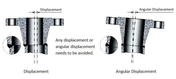
This may lead to issue during installation of thermowell.

Hence, mock-up needs to be done prior to steam blowing only so that if any minor grinding or surface finish is required in the nozzle same may be done.

Read Next:

  • Heat Tracing
  • Steam Tracing
  • Burner Safety
  • Role of Flow Meter
  • Impulse Line Test


Don't Miss Our Updates
Be the first to get exclusive content straight to your email.
We promise not to spam you. You can unsubscribe at any time.
Invalid email address
You've successfully subscribed !
Explain Operation of the Lamp Circuit ?
What is Cable Schedule and Junction Box Schedule?
System Architecture and Process Control Systems Philosophy
How to Avoid Process Downtime ?
Zener Diode Voltage Regulators
Share This Article
Facebook Whatsapp Whatsapp LinkedIn Copy Link
Share
Leave a Comment

Leave a Reply Cancel reply

Your email address will not be published. Required fields are marked *

Stay Connected

128.3kFollowersLike
69.1kFollowersFollow
208kSubscribersSubscribe
38kFollowersFollow

Categories

Recent Comments

  • MIHARITSOA Aina Sitraka on Top Non-PLC Certification Courses for Automation Professionals
  • Vaishnavi on Free Instrumentation Course for Trainee Engineers
  • anuj kapoor on DCS Program to Maintain Draft in Furnace
  • anuj kapoor on IoT based Smart Boiler Control System with Cloud PLC and SCADA

Related Articles

Loop Diagram

15 Loop Diagram Questions

Insulation of Thermowell

Facts on Thermowell Insulation Thickness

Selecting A Pneumatic Manifold

How to Select a Pneumatic Manifold

Fail Safe Switch Circuit

Basics of Fail-safe Circuits

Impulse Line Problems

What are Impulse Lines? – Impulse Line Problems & Solutions

Instrument Junction Box Specification

Instrument Junction Box Specification

Instrumentation and Control General Specifications

Instrumentation and Control (I&C) General Specifications

Pressure Switch Terminology

Pressure Switch Terminology

More Articles

Proximity Switch Working Animation

Proximity Switch Working Animation

100 Instrumentation Questions

100 Instrumentation Basics Questions

Selecting the Best Inductive or Capacitive Sensor

Selecting the Best Inductive or Capacitive Sensor

Foundation Fieldbus Tutorials

Foundation Fieldbus Tutorials

Comparison of MOSFET and BJT

Comparison of MOSFET and BJT

Flexible Input Output Modules

Flexible Input Output Modules

System architecture

Types of System Architecture used in Industrial Automation

basic-electronics-questions-answers

Basic Electronics Questions & Answers

Follow US
All rights reserved. Reproduction in whole or in part without written permission is prohibited.
Welcome Back!

Sign in to your account

Username or Email Address
Password

Lost your password?