Instrument Process Datasheet (IPDS)
Instrument Process Datasheet (IPDS) document plays a vital role in determining the type of instrument required to achieve the required parameters of the process. Instrumentation helps in better process monitoring and enhanced safety operation in plant
Contents
Process Engineer is responsible for providing basic process inputs & critical process information in the IPDS. It is sent to Instrumentation to do further works related to Instruments.
Instrument Process Data Sheet (IPDS) is developed by the process engineer. This information enables the Instrumentation & Control engineer to prepare documentation required for inquiry and purchase of instruments.
Types of Instruments used in Process Industry:
- Temperature (Gauge / Transmitter / Controller / Switch)
- Pressure (Gauge / Transmitter / Controller / Switch)
- Level (Gauge / Transmitter / Controller / Switch)
- Flow (Transmitter / Controller / Switch)
- Analyzers (Transmitter / Controller / Switch)
The following information is required to prepare IPDS:
- Instrument Tag Number
- P&ID Number
- Fluid name
- Nature of fluid
- Location
- Flowrate / Liquid level
- Operating & Design Conditions (Pressure & Temperature)
- Fluid Properties
- Hazardous Area Classification
- Temperature Class
- Alarm Set Points
- The specific type of Instruments (If any)
- Dielectric Constant
- MOC (Material of Construction)
- Insulation Requirement
- Valve Specification Requirement
The key things to consider while selecting the Instrument:
- Accuracy
- Repeatability
- Rangeability
- Ease in Installation
- Calibration
- Turndown Ratio
- Density Compensation
Reference Documents required for the preparation of IPDS:
- Process Design Basis Report
- P&ID
- Process Datasheet
- Line-list
- Heat & Mass Balance
- Calculation Report
- Hazardous Area Classification Diagram
- Vendor Catalog
- Instrument Specification
- Codes & Standards
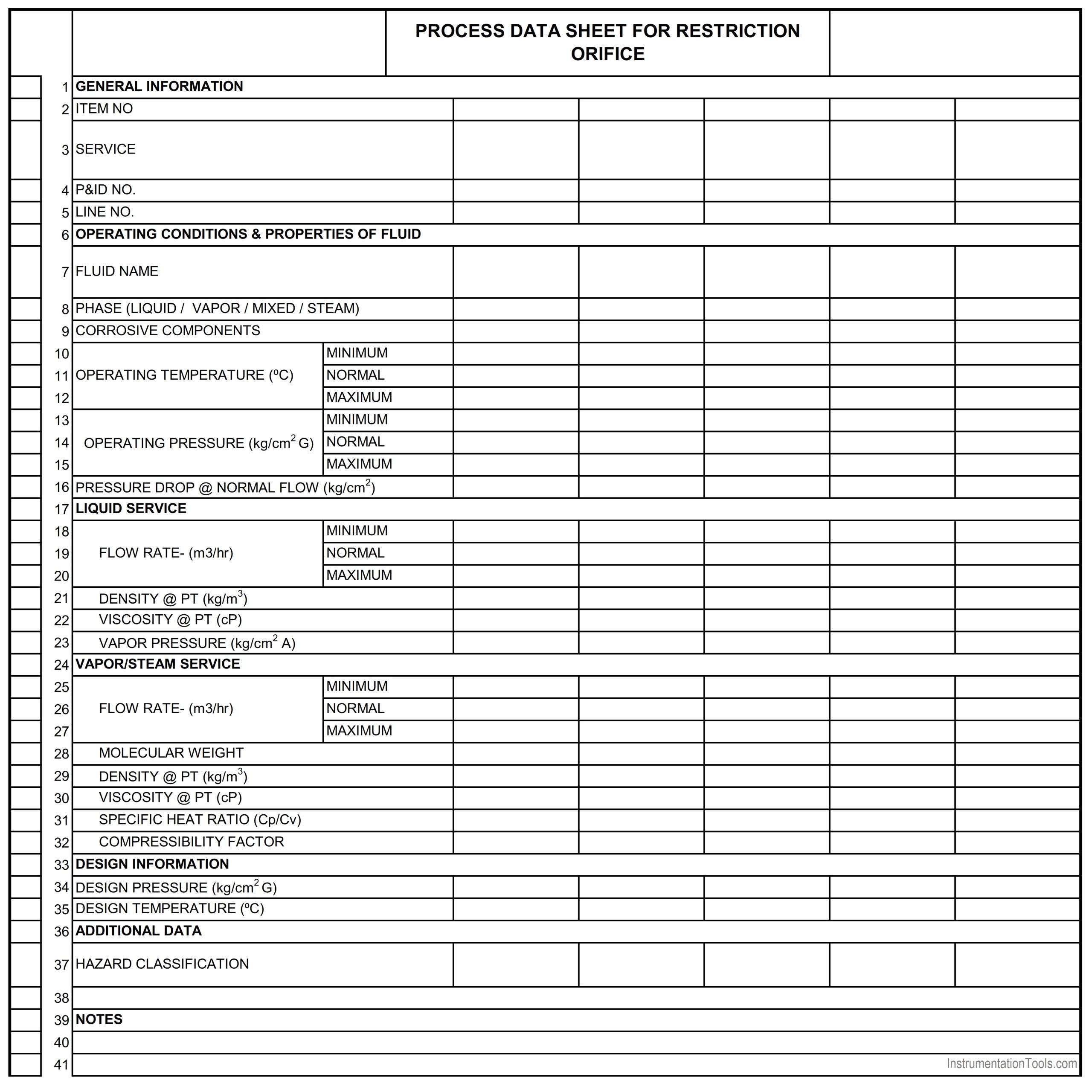
Example Instrument Process Datasheet for Restriction Orifice
Interest to add any further points? Share with us through below comments section.
Author: Kalpit Patel
Read Next:
- What is Static Grounding?
- What is the Safety System?
- Hazardous Area Classification
- Non-Intrinsic Safe Cables
- What is Inter Discipline Check?


Can you please make some YouTube video’s on data sheet explanation for all instrumentation device’s like PT TT FT LT ORIFICE, THERMOWEL, FLOW NOZZLE AND ETC
And also make some videos on what are the standards can we follow for while selecting the instrument each instrument’s wise ,I really excited to learn those thing’s
Can you please teach me instrumentation Design through any online media.