Each team must calibrate the transmitter (“trim” both the sensor and the output) to ensure it interprets pressure accurately and outputs an accurate current.
Then, each team member must configure the transmitter for a unique range (set the LRV and URV parameters) and scale the indicator (or indicating controller) to register in the proper engineering units (e.g. a pressure transmitter ranged for 30 to 70 PSI should actually register 30 to 70 PSI back at the control room display).
The accuracy of this ranging will be checked by the instructor by applying random air pressures to the transmitter while each student verifies the indicator display.
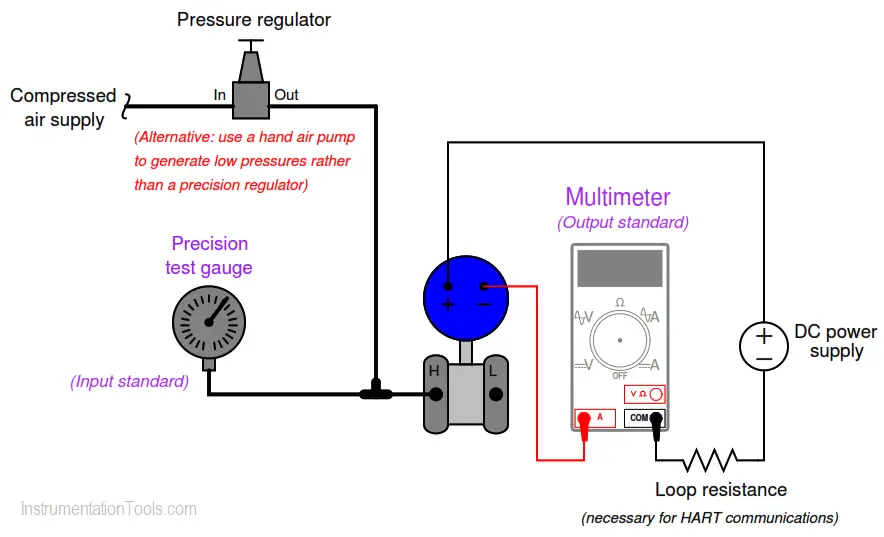
As in all cases where an instrument must be calibrated, you will need to check the instrument’s response against one or more standards.
In this case, the ideal standard to use for setting the input pressure to the transmitter is a precision test gauge (either mechanical or electronic), and the ideal standard to use for measuring the transmitter’s electronic output signal is a multimeter configured to measure DC milliamps:
The difference between “calibrating” a transmitter and “ranging” a transmitter is confusing to many students. With legacy-style analog transmitters, calibrating and ranging are one and the same. With modern digital instruments, calibration and ranging are separate tasks.
To calibrate a digital instrument means to subject it to a known (standard) stimulus and adjust the “trim” settings to ensure the instrument’s microprocessor accurately recognizes that stimulus condition. To “range” a digital instrument means to define the values of measurement for its 0% and 100% scale points. For more information on this distinction, refer to the “Instrument Calibration” article.
Document the accuracy of your transmitter’s sensor trim before and after adjustment in this table, at five different points throughout its sensing range using these two tables. Error in percent of span is calculated by dividing the difference between actual and ideal signal values by the span of the signal range:
When finished calibrating your team’s transmitter, be sure to place a calibration tag on it showing the range and the date it was calibrated.
A set of calibration tags are given here, which you may tape to the transmitter:
Each student, however, must individually re-range the transmitter and the receiving instrument (indicator, controller, and/or recorder). Re-ranging a digital instrument is a brief procedure using either a HART communicator or a computer-based tool such as Yokogawa PRM, Emerson AMS (if the instrument is connected to a host system with that software).
Each student’s ranging is confirmed by the instructor by applying random pressures to the transmitter and verifying that the indicating controller reads the same (to within ± 1% of span).
This is also a good opportunity for students to demonstrate the use of the transmitter’s valve manifold, showing how to “block in” the transmitter so it does not “see” process pressure.
Share your answers with us through the below comments section.
Read Next:
Credits: Tony R. Kuphaldt
PLC ladder logic design to control 3 motors with toggle switch and explain the program…
VFD simulator download: Master the online tool from the Yaskawa V1000 & programming software for…
The conveyor sorting machine is widely used in the packing industries using the PLC program…
Learn the example of flip-flop PLC program for lamps application using the ladder logic to…
In this article, you will learn the STAR DELTA programming using PLC controller to start…
Lube oil consoles of rotary equipment packages in industrial process plants are usually equipped with…


