Inst ToolsInst ToolsInst Tools
  • Courses
  • Automation
    • PLC
    • Control System
    • Safety System
    • Communication
    • Fire & Gas System
  • Instrumentation
    • Design
    • Pressure
    • Temperature
    • Flow
    • Level
    • Vibration
    • Analyzer
    • Control Valve
    • Switch
    • Calibration
    • Erection & Commissioning
  • Interview
    • Instrumentation
    • Electrical
    • Electronics
    • Practical
  • Q&A
    • Instrumentation
    • Control System
    • Electrical
    • Electronics
    • Analog Electronics
    • Digital Electronics
    • Power Electronics
    • Microprocessor
  • Request
Search
  • Books
  • Software
  • Projects
  • Process
  • Tools
  • Basics
  • Formula
  • Power Plant
  • Root Cause Analysis
  • Electrical Basics
  • Animation
  • Standards
  • 4-20 mA Course
  • Siemens PLC Course
Reading: Why are Impulse Lines often Installed in a Sloping Manner?
Share
Font ResizerAa
Inst ToolsInst Tools
Font ResizerAa
  • Courses
  • Design
  • PLC
  • Interview
  • Control System
Search
  • Courses
  • Automation
    • PLC
    • Control System
    • Safety System
    • Communication
    • Fire & Gas System
  • Instrumentation
    • Design
    • Pressure
    • Temperature
    • Flow
    • Level
    • Vibration
    • Analyzer
    • Control Valve
    • Switch
    • Calibration
    • Erection & Commissioning
  • Interview
    • Instrumentation
    • Electrical
    • Electronics
    • Practical
  • Q&A
    • Instrumentation
    • Control System
    • Electrical
    • Electronics
    • Analog Electronics
    • Digital Electronics
    • Power Electronics
    • Microprocessor
  • Request
Follow US
All rights reserved. Reproduction in whole or in part without written permission is prohibited.
Inst Tools > Blog > Pressure Measurement > Why are Impulse Lines often Installed in a Sloping Manner?

Why are Impulse Lines often Installed in a Sloping Manner?

The impulse lines are often installed in a slopping manner and we will learn the reason for the common practice of installing at an angle.

Last updated: August 27, 2023 12:28 pm
Editorial Staff
Pressure Measurement
1 Comment
Share
4 Min Read
SHARE

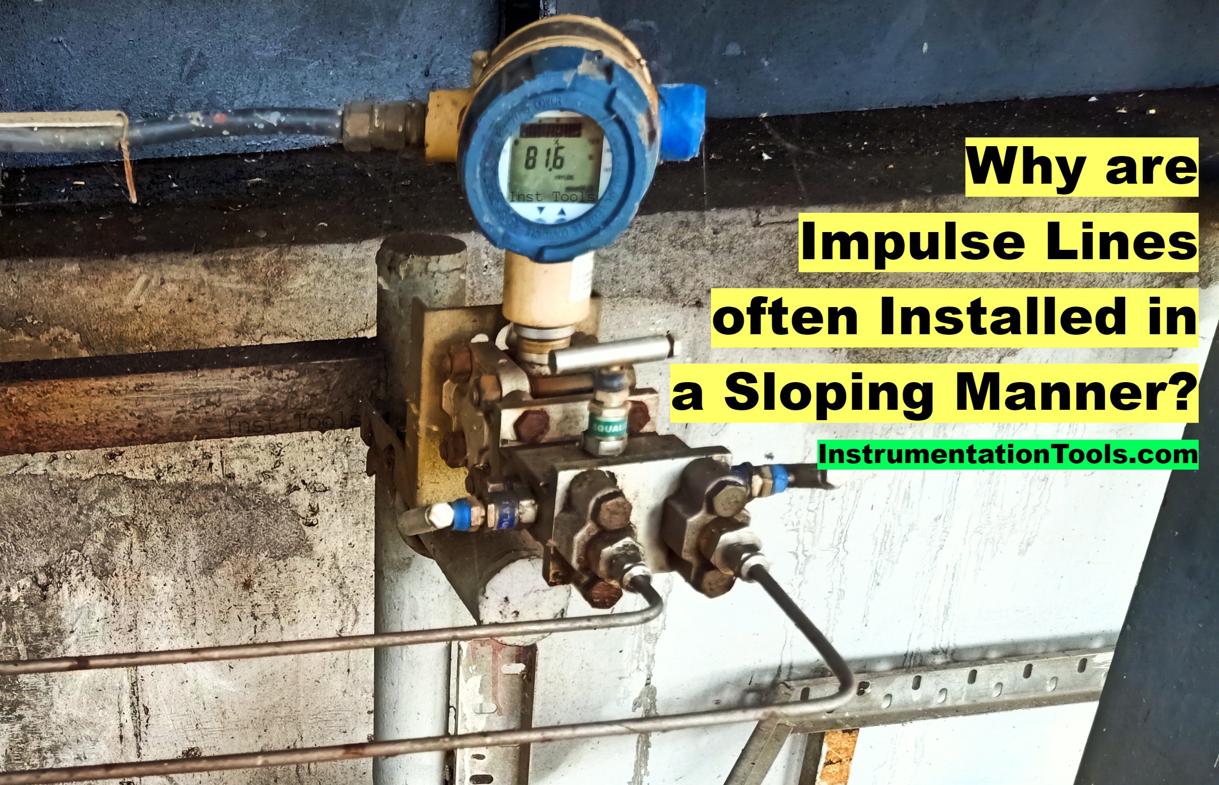
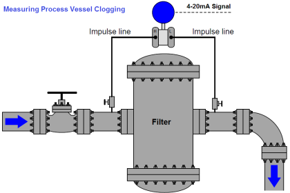
Impulse lines transmit pressure signals from the main process line to pressure measurement instruments. The impulse lines are often installed in a slopping manner and in this article, we will learn the reason for the common practice of installing the impulse lines at an angle.

Contents
Sloping Impulse LinesLiquid DrainageGas VentingAvoiding BlockagesTemperature ConsiderationsAvoiding the Water Hammer EffectMaintaining AccuracyEase of MaintenanceImportant Notes on Impulse LinesAdvantagesConclusion

Sloping Impulse Lines

The sloping impulse lines have many uses in industrial measurement applications. Some of them are mentioned below.

Why are Impulse Lines often Installed in a Sloping Manner (Angle)

Liquid Drainage

In gas or steam applications, condensation can occur within the impulse lines. A proper impulse line slope ensures that the condensed liquids can easily drain, avoiding any accumulation that may lead to erroneous readings.

Gas Venting

In liquid applications, trapped air or other gases can distort the pressure signal. An impulse line slope in the opposite direction allows these gases to vent towards the instrument side, maintaining accurate pressure transmission.

Avoiding Blockages

A sloping design ensures that particulates or substances that may solidify don’t settle and clog the impulse lines. This maintains the integrity of the pressure signal and avoids maintenance challenges.

Temperature Considerations

The slope assists in handling temperature-induced effects, ensuring that phase changes do not interfere with pressure readings.

Avoiding the Water Hammer Effect

Impulse pipe sloping design can help avoid the sudden transport of liquid through the impulse line, leading to pressure surges known as the water hammer effect, which can be damaging to instruments.

Maintaining Accuracy

The sloping installation helps mitigate various effects that can cause inaccuracies in pressure readings, ensuring more reliable and accurate measurements.

Ease of Maintenance

The slope facilitates easier purging and cleaning of the lines, essential for maintaining the measurement system.

Important Notes on Impulse Lines

The direction of the slope depends on the type of fluid. For gases or steam, the slope is generally towards the process, while for liquids, it is towards the instrument.

The angle of the slope must be carefully chosen based on fluid properties and potential issues like condensation, solidification, or trapped gases.

Proper installation practices must be followed to ensure that the slope is maintained throughout the impulse line.

Advantages

  • The sloping installation enhances the accuracy of pressure readings by mitigating potential errors caused by trapped fluids or solidified substances.
  • The design facilitates easier cleaning and maintenance, contributing to a more efficient and reliable system.
  • The design must consider factors such as the nature of the process fluid, temperature variations, pressure ratings, and the specific requirements of the application.

Conclusion

The practice of installing impulse lines in a sloping manner is rooted in sound engineering principles. It’s an essential aspect of design that takes into account fluid behavior, temperature effects, system reliability, and ease of maintenance.

Whether for liquid, gas, or steam applications, the slope in impulse lines ensures that pressure signals are transmitted accurately, efficiently, and without disruption. This seemingly simple design choice embodies the complexity and precision of modern process engineering, showcasing the intricate interplay of physics, materials science, and industrial design.

If you liked this article, then please subscribe to our YouTube Channel for Instrumentation, Electrical, PLC, SCADA, and Industrial Automation video tutorials.

You can also follow us on Facebook and Twitter to receive daily updates.

Read Next:

  • Impulse Piping for Field Instruments
  • Pressure Transmitters Purge Lines
  • Impulse Tubing Leak Test Checks
  • Transmitter Heat-traced impulse line
  • DP Transmitter Wet Leg Questions
Don't Miss Our Updates
Be the first to get exclusive content straight to your email.
We promise not to spam you. You can unsubscribe at any time.
Invalid email address
You've successfully subscribed !

Continue Reading

Bellows Pressure Sensors Working Principle Animation
Absolute Pressure Gauges Principle
What is Hammer Effect in Gauges ?
Helix and Spiral Tubes – Pressure Sensor
Pressure Transmitters Heat-traced impulse lines
Basics of Differential Pressure Transmitters
Share This Article
Facebook Whatsapp Whatsapp LinkedIn Copy Link
Share
1 Comment
  • Mi says:
    August 29, 2023 at 10:43 am

    Thank you, it was so helpful. Please put some picture to illuminate “gas, liquid, …” types of installation.

    Reply

Leave a Reply Cancel reply

Your email address will not be published. Required fields are marked *

Stay Connected

128.3kFollowersLike
69.1kFollowersFollow
210kSubscribersSubscribe
38kFollowersFollow

Categories

Explore More

Well Manometer Principle
How to Read Gauge Analog Scales
Bellows
15 HART Communicator Questions
Metal Foil Strain Gauge Principle
PLC Raw Count Calculation for Pressure Transmitter
Impulse Line – Purpose & Tapping Point Location
Bellows, Diaphragms and Bourdon Tubes

Keep Learning

Pressure Sensor Temperature Effects

Temperature Compensation for Pressure Measurement

Pressure Transmitter Calibration Procedure

Pressure Transmitter Calibration Procedure

Absolute and Gauge Pressure

Difference Between Absolute and Gauge Pressure

Force Balance Pressure Transmitters

Pneumatic Pressure Transmitters Principle

bourdon-tube-pressure-gauge-working-animation

Working Principle of Pressure Gauge

Installation and Calibration of Pressure Transmitter

Installation and Calibration of Pressure Transmitter

Diaphragm Seal Transmitters Errors

Diaphragm Seal Transmitters Errors

Submersible Pressure Transmitter

What is a Submersible Pressure Transmitter? Principle, Advantages

Learn More

Difference Between LAN and WAN Networks

Difference Between LAN and WAN Networks

Cable Shielding - Purpose, Selection, Grounding

Cable Shielding – Purpose, Selection, Grounding

Vibration Measurement Sensors

Types of Sensors used in Vibration Measurement

Industrial Instruments Questions and Answers

Industrial Instruments Questions and Answers

Questions and Answers on Motors and Generators

HT Motor Problem appears after Disassembly and Reassembly

RF-Capacitance Level Switch Principle

RF Capacitance Level Switch Working Principle

Identify Instrumentation Terms in Water Supply System

Identify Instrumentation Terms in Water Supply System

Difference Between Isolator and Circuit Breaker

Difference Between Isolator and Circuit Breaker

Menu

  • About
  • Privacy Policy
  • Copyright

Quick Links

  • Learn PLC
  • Helping Hand
  • Part Time Job

YouTube Subscribe

Follow US
All rights reserved. Reproduction in whole or in part without written permission is prohibited.
Welcome Back!

Sign in to your account

Username or Email Address
Password

Lost your password?