Inst ToolsInst ToolsInst Tools
  • Courses
  • Automation
    • PLC
    • Control System
    • Safety System
    • Communication
    • Fire & Gas System
  • Instrumentation
    • Design
    • Pressure
    • Temperature
    • Flow
    • Level
    • Vibration
    • Analyzer
    • Control Valve
    • Switch
    • Calibration
    • Erection & Commissioning
  • Interview
    • Instrumentation
    • Electrical
    • Electronics
    • Practical
  • Q&A
    • Instrumentation
    • Control System
    • Electrical
    • Electronics
    • Analog Electronics
    • Digital Electronics
    • Power Electronics
    • Microprocessor
Search
  • Books
  • Software
  • Projects
  • Process
  • Tools
  • Basics
  • Formula
  • Power Plant
  • Root Cause Analysis
  • Electrical Basics
  • Animation
  • Standards
  • 4-20 mA Course
  • Siemens PLC Course
Reading: Identify Problem with Oily Water Filter Instrumentation
Share
Notification Show More
Font ResizerAa
Inst ToolsInst Tools
Font ResizerAa
  • Courses
  • Design
  • PLC
  • Interview
  • Control System
Search
  • Courses
  • Automation
    • PLC
    • Control System
    • Safety System
    • Communication
    • Fire & Gas System
  • Instrumentation
    • Design
    • Pressure
    • Temperature
    • Flow
    • Level
    • Vibration
    • Analyzer
    • Control Valve
    • Switch
    • Calibration
    • Erection & Commissioning
  • Interview
    • Instrumentation
    • Electrical
    • Electronics
    • Practical
  • Q&A
    • Instrumentation
    • Control System
    • Electrical
    • Electronics
    • Analog Electronics
    • Digital Electronics
    • Power Electronics
    • Microprocessor
Follow US
All rights reserved. Reproduction in whole or in part without written permission is prohibited.
Inst Tools > Blog > Practical Questions > Identify Problem with Oily Water Filter Instrumentation

Identify Problem with Oily Water Filter Instrumentation

An operator reports a problem with the oily water filter instrumentation in this process. The PDIR and PG indicate different readings.

Last updated: September 7, 2020 12:31 pm
Editorial Staff
Practical Questions
No Comments
Share
1 Min Read
SHARE

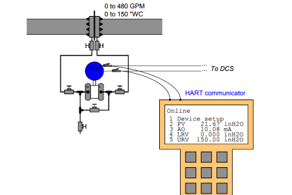
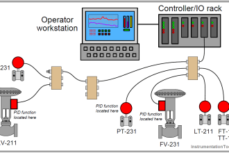
An operator reports a problem with the oily water filter instrumentation in this process: PDIR-136 indicates a differential pressure of 1.8 PSID, while PG-417 reads 12.5 PSI and PG-421 reads 11.3 PSI.

Your first test is to check the indication of PIR-137, and you see that it reads 12.6 PSI:

Oily Water Filter Instrumentation

Identify Problem with Oily Water Filter Instrumentation

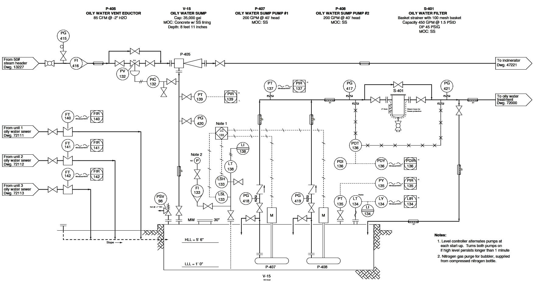
Identify the likelihood of each specified fault in this process. Consider each fault one at a time (i.e. no coincidental faults), determining whether or not each fault could independently account for all measurements and symptoms in this process.

Identify the below faults that are possible or Impossible?

  • Upstream filter block valve partially shut
  • Downstream filter block valve partially shut
  • PDT-136 calibration error
  • PT-137 calibration error
  • PG-417 calibration error
  • PG-421 calibration error
  • Filter drain valve to sump left open

Explain why the idea to check PIR-137 was a good first diagnostic test.

Share your answers with us through the below comments section.

Read Next:

  • DP Transmitter with 5 Way Manifold
  • Filled-bulb Temperature Sensor
  • DP Transmitter Auto Calibration
  • Manometer Measurement Accuracy
  • Process Control High-Level Alarm

Credits: Tony R. Kuphaldt

Don't Miss Our Updates
Be the first to get exclusive content straight to your email.
We promise not to spam you. You can unsubscribe at any time.
Invalid email address
You've successfully subscribed !

Continue Reading

Tank uses 3 Pressure Transmitters to Measure Level & Density
Stilling Well in Interface Level Measurement System
Determine Calibration Range of Pneumatic Pressure Transmitter
PLC Switch Actuation Status
How Much Pressure Indicated by Micromanometer?
Pneumatic Relay Questions
Share This Article
Facebook Whatsapp Whatsapp LinkedIn Copy Link
Share
Leave a Comment

Leave a Reply Cancel reply

Your email address will not be published. Required fields are marked *

Stay Connected

128.3kFollowersLike
69.1kFollowersFollow
210kSubscribersSubscribe
38kFollowersFollow

Categories

Explore More

DP Transmitter Error Calculations
Programmable Logic Controller (PLC) Questions and Answers – 14
Practical Process Control System Questions & Answers – 6
What is the Simple Alternative Vessel Level Indication?
DP Transmitter Located 10 feet Beneath the Vessel
Upgrading the Electrical System in an Automobile
Identify Instrumentation Terms in Water Supply System
Galileo Thermometer

Keep Learning

calibrating low-pressure instrument

Simulate Different Values for Pressure Instrument Under Test

burner management system P&ID

Solenoid Valves Questions & Answers – 1

Double Block and Bleed Valves Opening or Closing Sequence

Double Block and Bleed Valves Opening or Closing Sequence

Electronic Pressure Sensor with Bourdon Tube and LVDT

Electronic Pressure Sensor with Bourdon Tube and LVDT

Calculate the Magnitude of Hydrostatic Pressure

Calculate the Magnitude of Hydrostatic Pressure

valve control system

Solenoid Valves Practical Problems

Calculate voltage across RTD

Resistance Temperature Detector (RTD) Questions – 2

Inclined Water Manometer

How much Pressure is applied to Inclined Water Manometer?

Learn More

Factors to Consider When Choosing Power Tools

Factors to Consider When Choosing Power Tools

What is a Pilot Valve?

What is a Pilot Valve? When do we use a Pilot Valve?

Voltage and Current Phase Relationships in an Inductive Circuit

Voltage and Current Phase Relationships in an Inductive Circuit

Voltage Control Methods at Distribution System

Factors affect Voltage Level Selection in Service System

Bently Nevada 3500 Machinery Protection Systems

Bently Nevada 3500 Machinery Protection Systems Hardware Modules

Center Tapped Full Wave Rectifier Operation

Center Tapped Full Wave Rectifier Operation

Manufacturing Execution System in Industrial Automation

Manufacturing Execution System (MES) in Industrial Automation

HIPPS Operating Philosophy

Understanding High Integrity Pressure Protection Systems (HIPPS)

Menu

  • About
  • Privacy Policy
  • Copyright

Quick Links

  • Learn PLC
  • Helping Hand
  • Part Time Job

YouTube Subscribe

Follow US
All rights reserved. Reproduction in whole or in part without written permission is prohibited.
Welcome Back!

Sign in to your account

Username or Email Address
Password

Lost your password?