Inst ToolsInst ToolsInst Tools
  • Courses
  • Automation
    • PLC
    • Control System
    • Safety System
    • Communication
    • Fire & Gas System
  • Instrumentation
    • Design
    • Pressure
    • Temperature
    • Flow
    • Level
    • Vibration
    • Analyzer
    • Control Valve
    • Switch
    • Calibration
    • Erection & Commissioning
  • Interview
    • Instrumentation
    • Electrical
    • Electronics
    • Practical
  • Q&A
    • Instrumentation
    • Control System
    • Electrical
    • Electronics
    • Analog Electronics
    • Digital Electronics
    • Power Electronics
    • Microprocessor
  • Request
Search
  • Books
  • Software
  • Projects
  • Process
  • Tools
  • Basics
  • Formula
  • Power Plant
  • Root Cause Analysis
  • Electrical Basics
  • Animation
  • Standards
  • 4-20 mA Course
  • Siemens PLC Course
Reading: 4-20mA Junction Box versus Fieldbus (FF) Junction Box
Share
Notification Show More
Font ResizerAa
Inst ToolsInst Tools
Font ResizerAa
  • Courses
  • Design
  • PLC
  • Interview
  • Control System
Search
  • Courses
  • Automation
    • PLC
    • Control System
    • Safety System
    • Communication
    • Fire & Gas System
  • Instrumentation
    • Design
    • Pressure
    • Temperature
    • Flow
    • Level
    • Vibration
    • Analyzer
    • Control Valve
    • Switch
    • Calibration
    • Erection & Commissioning
  • Interview
    • Instrumentation
    • Electrical
    • Electronics
    • Practical
  • Q&A
    • Instrumentation
    • Control System
    • Electrical
    • Electronics
    • Analog Electronics
    • Digital Electronics
    • Power Electronics
    • Microprocessor
  • Request
Follow US
All rights reserved. Reproduction in whole or in part without written permission is prohibited.
Inst Tools > Blog > Animation > 4-20mA Junction Box versus Fieldbus (FF) Junction Box

4-20mA Junction Box versus Fieldbus (FF) Junction Box

Last updated: June 19, 2019 11:24 am
Editorial Staff
Animation Control Systems Guest Articles
18 Comments
Share
3 Min Read
SHARE

How will a field JB of conventional 4-20mA connection look different from that of FF JB.

Conventional Junction box

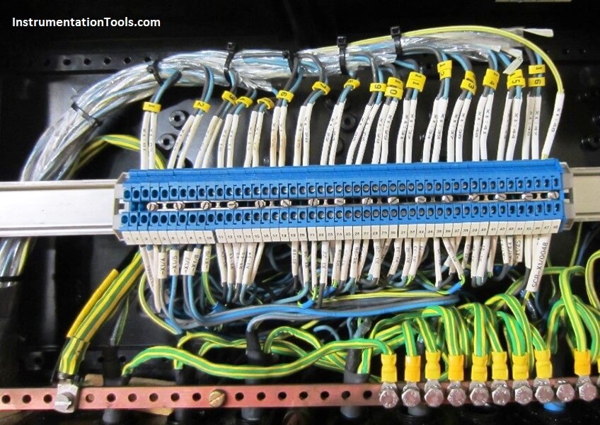
Convectional Junction box contains Terminal Strip and Earth Strip/earth bus bar only.

Instruments field pair / core cable (From Instruments to Junction Box for transmitters, switches, valves, solenoid valve etc.) is terminated at one side of terminal strip and multi-pair cables (From Junction box to Marshalling cabinet/system cabinet/control panel) are terminated at other side of terminal strip.

The shield/screen of cable is terminated on Earth strip or terminals based on project philosophy.

Field Instruments Junction Box

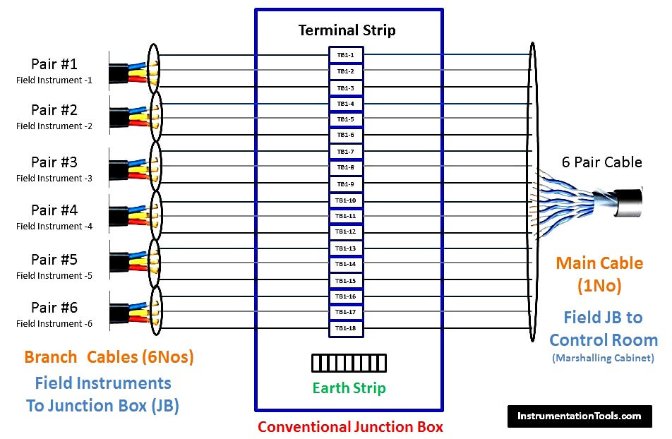
Field Instruments (4-20mA) to Conventional Junction Box Animation :
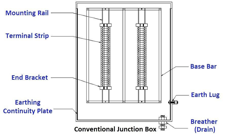
Field Instruments Junction Box Animation

Junction Box Parts

Junction Box

Junction Box External View

Junction Box External Parts

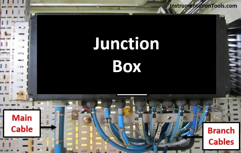
Junction Box Internal View

Junction Box Wiring

FF (Foundation Fieldbus) Junction box

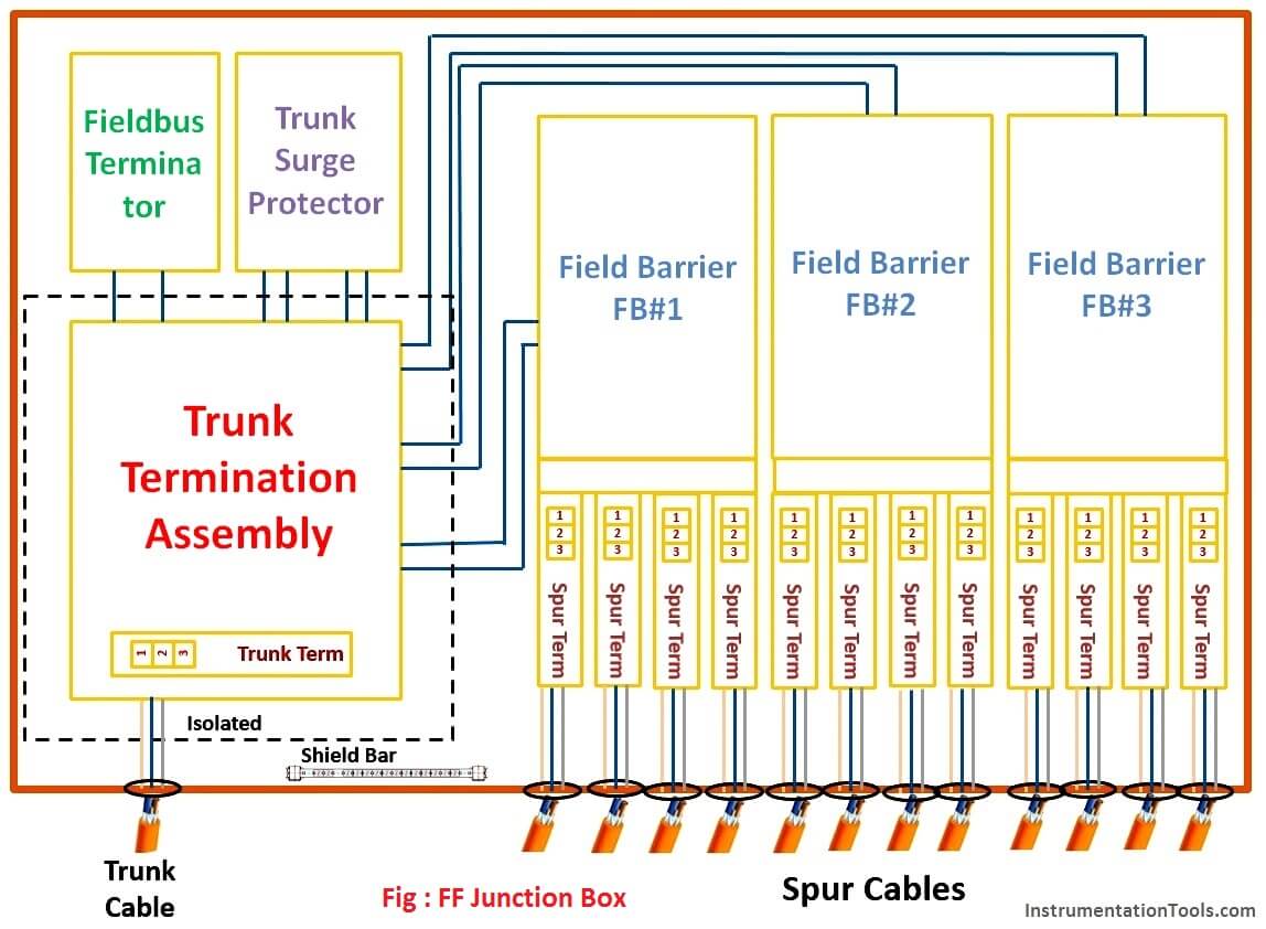
FF Junction box generally contains

  1. Spur termination board and Field Barrier
  2. Trunk Termination Assembly
  3. Surge Protector
  4. Fieldbus terminator
  5. Trunk Termination board
  • A typical FF JB arrangement is shown in Fig below. The internal layout of components may vary for different designs and suppliers, however the components remains same mostly.
  • The cable connected to field instrument (transmitters, switches, valves, solenoid valve etc.) is termed as Spur Cable and cable connected to control system is termed as Trunk Cable.
  • The example used here is High Power Trunk concept, where Trunk is non IS and Spur is IS (IS – Intrinsically Safe).
  • As Trunk is non–IS, trunk termination assembly is physically Isolated by means of separator plate section inside JB to provide separation between IS and Non IS signals.
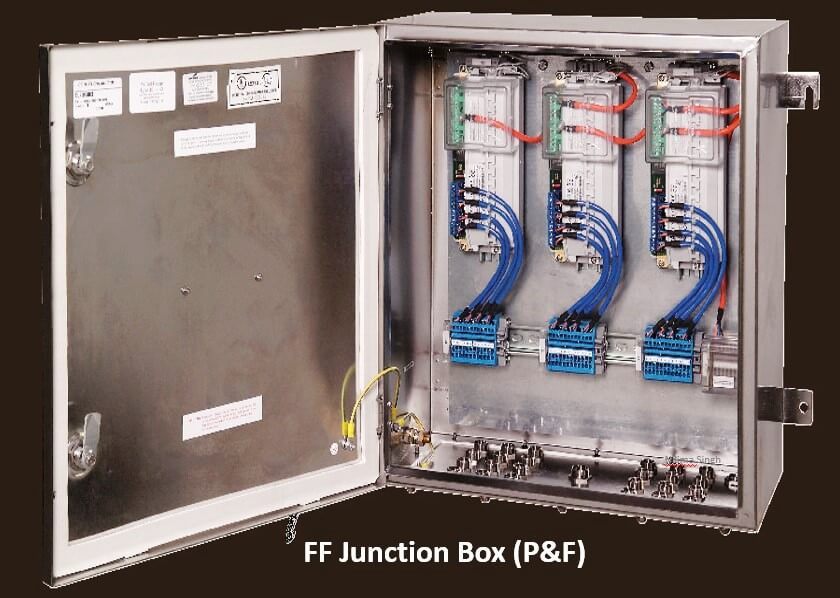
  • Internal wiring is done by FF-JB supplier. Field Engineer has to terminate Spur and Trunk cables at site on termination boards.
  • The FF JB design is based on segment design which will provide no of spurs and Trunk connected in single FF JB. Segment design is a separate topic of discussion hence not covered here.
  • In some cases temperature multiplexers are used to connect temperature Element on FF segment. These multiplexers are installed inside Junction box and this multiplexer JB is connected to FF JB as a spur like any other transmitter spur. A good design engineering practice is to limit 1 to 2 no. Multiplexer in a segment.

Fieldbus Junction Box

Fieldbus Signals Flow Animation : FF Field Instruments to FF JB, then to Host/Control Room

Fieldbus Signals Flow Animation

FF Junction Box

FF Junction Box

Also See : DCS/PLC Signal Flow Animation

Article by :
Nilima singh
Instrumentation and control Engineer
13 year experience in Detail engineering
Worked on various Refinery, Oil & Gas, Petrochemical and chemical projects
Don't Miss Our Updates
Be the first to get exclusive content straight to your email.
We promise not to spam you. You can unsubscribe at any time.
Invalid email address
You've successfully subscribed !

Continue Reading

Does Really a Safety Barrier is Important? – PLC DCS Systems
Types of Surge Control for Parallel Gas Compressors
Identify Faults in PID Control Loop
Oscillating Piston Flow Meters Working Principle
Process Control & Safety Systems Logics Implementing Cycle
MOS Type Gas Sensor Principle
Share This Article
Facebook Whatsapp Whatsapp LinkedIn Copy Link
Share
18 Comments
  • Karthikeyan M says:
    September 16, 2017 at 11:48 am

    No Words to say, Best Article, Now i got some idea on Fieldbus & 4-20ma Junction boxes. Amazing efforts. Very good animations. thank you

    Reply
  • Krishan lal says:
    September 19, 2017 at 4:02 am

    Very nice and good knowledge thanks

    Reply
  • Baba says:
    September 22, 2017 at 6:00 am

    I got a very nice information Thank you very much

    Reply
  • Anas Kadri says:
    October 11, 2017 at 7:05 am

    Best explanation 🙂

    But one question… trunk cable is shown just one .. can we use the spare trunk cable for redundancy purpose ??

    Reply
    • S Bharadwaj Reddy says:
      October 11, 2017 at 12:59 pm

      Hi Anas, Yes Trunk cable have two pairs, Second one is spare cable. Generally we don’t use redundancy, second trunk cable only for spare. Same already mentioned as Note in the animation.

      Reply
  • azetou says:
    October 11, 2017 at 3:03 pm

    Good job, thanks. However there is a little mistake : in the first picture, you wrote pairs for branch cables but you are showing triads.

    Reply
  • Jigar Rana says:
    October 12, 2017 at 5:18 am

    hello sir ,

    what is cascade loop and feedforward loop plz describe it with diagram

    Reply
    • S Bharadwaj Reddy says:
      October 12, 2017 at 5:23 am

      Hi, Please check CONTROL SYSTEM category, Already Available.

      Reply
  • JUSTIN says:
    October 12, 2017 at 6:53 am

    hello sir,

    Can you give us more detail knowledge on DCS systems functionality more on honeywell TDC 3000.

    Reply
  • Deepakkumar says:
    December 12, 2017 at 7:17 am

    what is the maximum distance between instrument to FF junction box and junction box to control room.

    Reply
  • Dodz says:
    March 24, 2018 at 4:12 pm

    Can you send me more about Foundation Field bus system like, the distance from instrument to FFJB and from FFJB to control room.
    What is segment in terms of FF system And clear wiring diagram from spur cables, internal wiring and to control room.
    HOw FF works.. thanks

    Reply
    • SABIR HUSSAIN says:
      December 11, 2022 at 12:58 am

      In the marshaling cabinet also gathering multiple trunk cables from different junction box and combined in one internal cable with one redundant and provide multiple communication to the DCS I/O’s cards

      Reply
  • Mk Chaudhary says:
    October 12, 2018 at 9:21 am

    It’s a great learning portal.

    Reply
  • Moses Kashimba says:
    December 20, 2018 at 9:54 am

    The information is so helpful, thank you.

    Reply
  • Ramprasad says:
    June 12, 2020 at 8:46 am

    we know that the general procedure for conventional wiring are shields are not terminated at the field side, whereas what is procedure do we follow in the FF concept. does shield termination at the field will be there or not.

    Reply
  • Aspak says:
    July 28, 2020 at 8:53 pm

    Thanks for the information.

    Reply
  • SABIR HUSSAIN says:
    December 11, 2022 at 12:50 am

    Hi,
    As I know that the solenoid required digital signal in on/off form to operate, so this (solenoid) can not be operated by FF fieldbus communication, but it is mentioned in this article,
    Please correct me if I’m wrong

    Reply
  • Jigar says:
    March 12, 2023 at 9:51 pm

    What is the use of temperature multiplexer in ff

    Reply

Leave a Reply Cancel reply

Your email address will not be published. Required fields are marked *

Stay Connected

128.3kFollowersLike
69.1kFollowersFollow
210kSubscribersSubscribe
38kFollowersFollow

Categories

Explore More

Proportional Controller Principle
Process Switches and Alarms
Basics of 4-20mA Current Loop
What is a Surge Protection Device? – Principle, Types, Advantages
Process Control Instrumentation
Turbine Flow Meters Animation
DeltaV System Configuration Changes and Download
Equivalent Logic Gates using PLC Ladder Diagrams

Keep Learning

Vortex Flow Meter Principle

Vortex Flow meter Animation

IACS Network

Remote Connectivity to Industrial Automation Systems

Override Control Functions

What is Override Control? – Need & Applications

Troubleshooting PLC Current Loops

Troubleshooting Current Loops with Voltage Measurement

Electrical-Switches-Working-Animation

Electrical Switches Working Animation

Switches, Repeaters, Bridges, Routers, Firewalls

Purpose of Gateways, Bridges & Routers in Networking

PLC Program for Alarm Indication in Process

PLC Program for Alarm Indication in Process Control

Control Room Design Guidelines

Control Room Design Guidelines

Learn More

GATE Instrumentation Questions and Answers

GATE Instrumentation Questions and Answers

Electrical Equipment Selection in Hazardous Area

Hazardous Areas in Industry – Electrical Equipment Selection

Nonlinear Control Systems

Construction of Phase -Trajectories

Zener Diode Limiter Working

Zener Diode Limiter

Ammonia Analyzer Working

Ammonia Analyzer Principle

Laser Doppler anemometer

Laser Doppler Anemometer

DC Motor Action

DC Motor Speed

Common Control Valve Problems

Troubleshooting Common Control Valve Problems

Menu

  • About
  • Privacy Policy
  • Copyright

Quick Links

  • Learn PLC
  • Helping Hand
  • Part Time Job

YouTube Subscribe

Follow US
All rights reserved. Reproduction in whole or in part without written permission is prohibited.
Welcome Back!

Sign in to your account

Username or Email Address
Password

Lost your password?