This article is about the PLC programming troubleshooting method. In industrial PLCs where thousands of inputs and outputs are used, and we know how lengthy PLC programs are, depends on the application or plant usage.
Some times, People may change the logic parameters unknowingly and it may lead to a fault. Even some faults are created during the logic design stage due to the complexity of the design. The siemens plc software has different handy tools available in it to troubleshoot the faults generated in the programs.
Faults can be like overlapping of addressing, multiple same output instances, memory bit address overlapping, many times a single program is used to work over and over, etc.
To find out such problems, there are four types of windows available in the siemens software which will help us to troubleshoot the issues.
They are:
Let discuss how to use them in our program for troubleshooting and where to find them in the software.
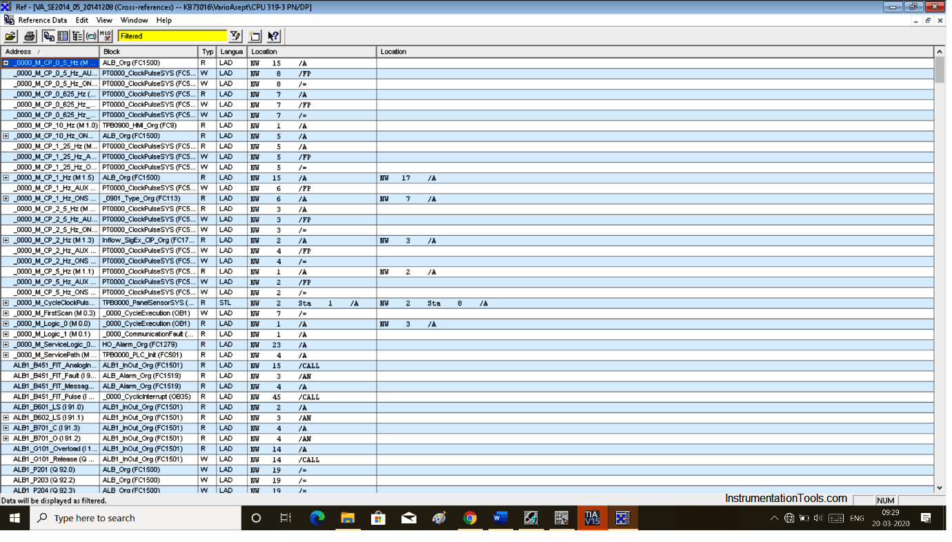
Cross-reference is used to find all the digital & analog inputs and outputs used in the logics. It will help us to know about the number of times the I/O’s are used in the program and also take users directly to the specific location of the I/O’s in the logic pages.
Here is an example of one of the programs, in which you can see how the cross-reference table looks like. It contains all the information like addressing, the language of the program, used inputs and outputs, etc.
When you want to know which block is used in programming then call structure is used.
This is a reversal of cross-reference function in which we get to know that how many times SFC, FB block are used in OB (Organization Block) and here we get to know that how many times OB used in SFC and FBs.
The assignment list is a very useful feature when it comes to knowing that how many inputs, outputs, timers and counters used in our application and how many of them are still remaining, so we can use them in future logics.
Dependency structure is used to show where each and every block used within the programming.
But in step 7 it won’t take you directly on location however in TIA PORTAL it will take you to the location where the program is written.
NOTE:
To open these windows in step 7, use the info as shown in Drawing. After clicking on display you have the options.
In TIA PORTAL, follow the below step shown in the drawing.
Author: Suhel Patel
If you liked this article, then please subscribe to our YouTube Channel for PLC and SCADA video tutorials.
You can also follow us on Facebook and Twitter to receive daily updates.
Read Next:
Learn an example PLC program to control a pump based on level sensors using ladder…
In the PLC timer application for security camera recording, when motion is detected then camera…
In this example, we will learn batch mixing with PLC ladder logic program using timer…
This PLC example on manufacturing line assembly is an intermediate-level PLC program prepared for the…
In this article, you will learn the PLC programming example with pushbutton and motor control…
This article teaches how to convert Boolean logic to PLC programming ladder logic with the…


View Comments
Realy good thanks