In this article, we will learn how to troubleshoot the control valve? Mention different problems and solutions of control valves in industries.
The problems in oil & gas, refining, fertilizer, Chlor-alkali, pulp & paper plants, etc., are different and peculiar to each process.
In the valve, the body and the internal organs, called “trim”, are those that suffer the consequences of the circulation of the fluid with which it is in contact, at the pressure and process temperature, giving rise to problems of corrosion, wear by abrasion, cavitation, noise, and vibrations.
Grouping the most typical situations we can have:
The trim is the heart of the valve; if the trim fails, everything fails. It is important to take care in the sizing and the correct selection of the type of trim, taking into account the characteristics of the fluid and the nature of the spill, but also the plug-seat-cage-stem materials that will define its resistance and durability is the reliability of control over time.
Other causes
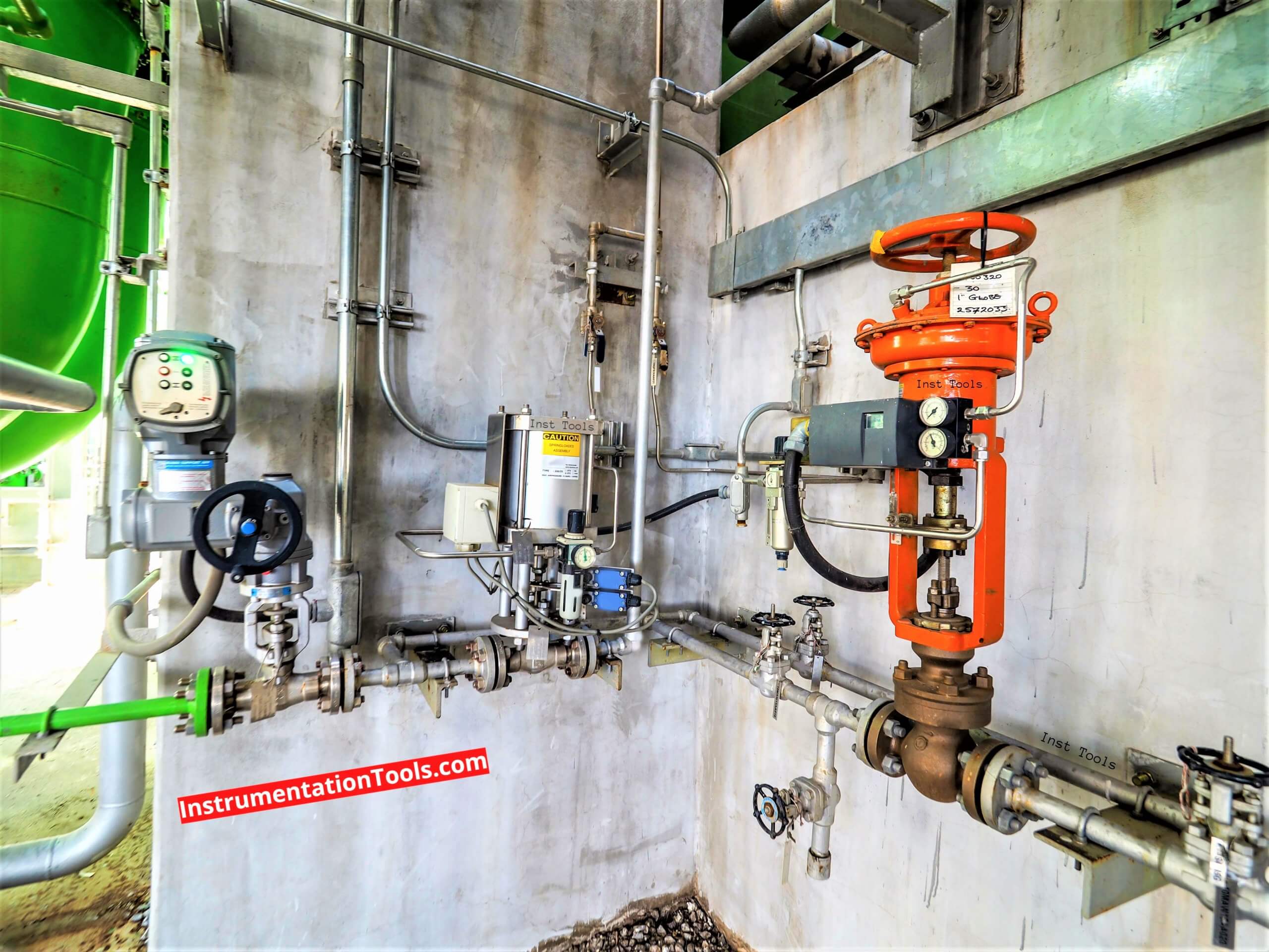
The control valve is the only element of the control loop that acts on the fluid, throttling its passage, causing pressure loss to be able to vary the flow, in response to the command signal from the Distributed Control System (DCS).
As per the data analysis, the valve occupies the most time, and approximately 45% -50% are due to problems in the body, and more specifically in the trim. The rest is distributed between actuator, positioner, and accessories.
These data must be interpreted as general, they can vary greatly depending on the process plant, nature of the fluids, operating conditions, operating regime, etc.
Chemical corrosion that attacks the entire surface of the metal and appears on all surfaces in contact with the fluid, although there may be areas of the valve, body-cover, affected in various ways by the effect of speed and/or turbulence.
Its appearance is that of a cavernous, rough, or pitted surface. Chemical corrosion is more difficult to avoid when dealing with a mixture of fluids. It also attacks transition zones between two materials, as is the case with welds, both in the manufacture of the valve and in its connection to the pipes, when they are for welded connections.
Pitting corrosion, typical of stainless steels in the presence of chlorides.
Galvanic corrosion when we have two materials of different potential. In some applications, such as oxygen gas, equipotential bonding is used.
For the body cover and trim, steels resistant to the fluids to be controlled will be used. Normally the body cover will be of a material similar in composition to the material of the pipe.
In the first place, the corrosion can affect the body-cover-trim if the materials have not been chosen well. It is a difficult phenomenon to deal with in some cases since small deviations in composition, liquid, temperatures, speed, etc. modify their aggressiveness.
During the material selection process, all possible types of corrosion must be evaluated, since in each process or type of plant some corrosive phenomena will appear more than others.
The phenomenon of abrasion should not be confused with the wear produced in the event of cavitation or flashing.
The abrasive effect of the impacts and the response of the materials is different. In some applications, there may be wear produced only by the effect of a high speed and it almost always materializes in the shutter and seat, although in some cases it affects the body depending on the design and direction of circulation.
Speed is an important factor to watch. Small variations in speed can produce very different wear.
Particulate abrasion is difficult to avoid as we cannot change the nature of the fluid. Its aggressiveness depends on the number of suspended particles, their size, and their hardness.
Small particles, but in a higher percentage in the fluid, can produce more wear than larger particles in a lower percentage. Hard steels are recommended in the trim.
Stainless Steel type 316, Monel K, Stellite (Cobalt-Chromium alloy), Carbide, Alumina, and Ceramics.
Eccentric rotary plug valves, with fairly normal alloyed or stainless steels, resist abrasion better than other designs with the more complicated passage.
In high abrasion situations: Bodies lined with ceramic trim, Zirconia, can be used in ball or plug valves.
With clean fluids, high speeds must also be avoided, which are the cause of wear on the body in the form of grooves in the same direction as the fluid circulation. They also produce vibrations that fatigue guides and are transmitted downstream of the valve. For this reason, it is recommended not to exceed 10 m / sec., with water or high percentages of water.
At high pressures such as in the energy sector, in the feedwater system, this value is lower and the bodies are calculated for an outlet velocity of about 5 – 7 m / sec.
The passage of a liquid fluid through a control valve can result in a subcritical or critical spill.
A critical spill, in the case of liquids, can cause cavitation or flash, which are two different phenomena. In the case of gases and steam, a critical spill manifests itself in the form of aerodynamic noise.
We will have cavitation if the thermodynamic conditions that produce it are met. The technician’s mission is to analyze the spill in the valve he is studying, starting from all possible working conditions, and to know how to find a type of control valve that avoids or minimizes the harmful effects that cavitation produces, depending on its intensity.
The appearance of cavities in the form of bubbles that, due to a simultaneous effect of implosion and micro jets, are mainly projected on the trim, causing severe wear resulting in a rough, porous, matt surface with loss of material. It can also affect the body, especially between the seat and the body.
If we have an application where there is cavitation, several things can be done.
When it is of moderate intensity, it can be resisted using hard materials in the trim: hardened or satellite steels.
Control it, using some special trim designs, that is, that the implosions and the critical jet is projected in an area that does not affect vital parts of the valve. This is valid under moderate differential pressure conditions, prior to good process analysis.
It is best to avoid it, selecting designs that prevent cavitation. Thus we protect the valve and maintain its performance in all working conditions that may occur in the process. In all cases, it will be monitored that the hydrodynamic noise is low.
If you liked this article, then please subscribe to our YouTube Channel for Instrumentation, Electrical, PLC, and SCADA video tutorials.
You can also follow us on Facebook and Twitter to receive daily updates.
Read Next:
Learn an example PLC program to control a pump based on level sensors using ladder…
In the PLC timer application for security camera recording, when motion is detected then camera…
In this example, we will learn batch mixing with PLC ladder logic program using timer…
This PLC example on manufacturing line assembly is an intermediate-level PLC program prepared for the…
In this article, you will learn the PLC programming example with pushbutton and motor control…
This article teaches how to convert Boolean logic to PLC programming ladder logic with the…

View Comments
Good article
I appreciate the author R jagan mohan rao for writing the detailed article
Than you
Please add few more points in comments regarding the subject, so as to make the article more fragrant.