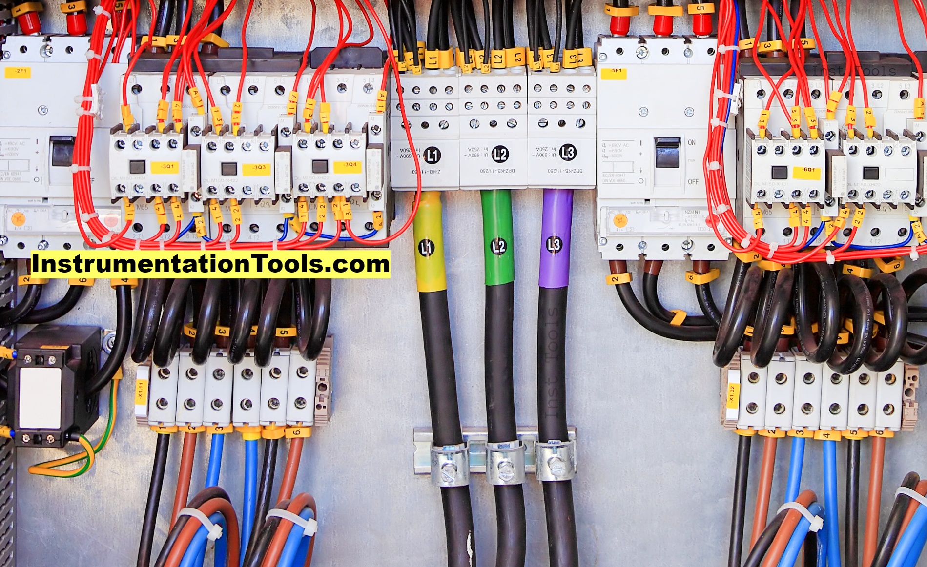
An electric wire has three types of connections – phase, neutral, and earth. Whenever a person deals with electric wires, it is necessary to identify which wire does what job and how to distinguish between them.
Often, people mislead in getting the right type of wire, and then it becomes difficult for them to troubleshoot the whole circuit. It is for this reason that it is necessary to identify the correct type of wire in a cable.
In this post, we will learn how to identify phase, neutral, and earth wires in an electrical power system.
Difference between Phase, Neutral, and Earth Wires
In an electrical circuit, current starts from the positive terminal to the load, and back to the source (negative terminal) through the load. The wire carrying current from the source is the positive wire or phase connection. It has all the current required for the load to operate. The current, after being consumed through the load, is returned back to the source through the negative wire or neutral connection.
A neutral wire thus has the return current, which is of a very small quantity. Now, as the current is flowing through a load, which is mostly a metal, some amount of current flows through the metallic body too. It can also be generated through leakage current from electromagnetic sources or noise. If someone touches the body accidentally, then he can get an electric shock.
To prevent this, a wire is connected from the metallic body to the earth pit or ground. This returns the leakage current back to the ground, which has zero potential. This is called earthing wire. So, in short, phase wire is the load current carrying wire, neutral wire is the return current carrying wire, and earthing wire is the electrical safety wire.
How to Check Phase, Neutral, and Earth Wires?
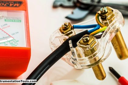
A very simple method of checking the wire is to connect a tester to the wire. If the tester glows, then that wire is the line wire and if it does not glow, then it is the neutral wire. But, it is to be noted that both the neutral and earth wire have a minimum or negligible amount of current in them.
So, it is difficult to identify if the wire is neutral or earth. So, this simple technique is just a method to check live wire normally. But, it is not the most reliable and efficient method to check which type of wire you are dealing with. Because, if you connect any wire anyhow and if there arises an accidental touch between them, then it can trip the circuit or even result in a huge spark.
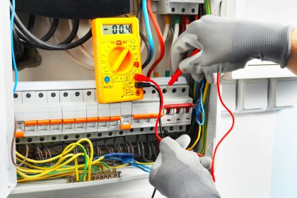
So, there are other proper methods to determine the type of wire connection. The very first method is checking with a multimeter. Between any two wires, if you get 230V AC reading on the multimeter, then it means one of the wires is obviously a phase wire.
Now, to identify the positive or negative one, read the value shown. If it is -230, then the red probe of the multimeter is connected to the negative wire, and the black probe of the multimeter is connected to the positive wire. If it is 230, then the red probe of the multimeter is connected to the positive wire, and the black probe is connected to the negative wire.
Now, we also know that both the neutral and earth have a very low to zero potential. So, this negative wire could be either a neutral wire or an earth wire. This needs to be sorted out in the next step.
If there are only two wires present in a connection, then the black wire is obviously a neutral one. The problem arises with three wires. This can also be solved by checking the AC voltage. The voltage between phase and neutral can be, for example, 230 V; but the voltage between phase and earth is usually on the higher side, mostly 238 V. There is a difference of usually 7-8 V between them.
The negative wire which shows higher voltage on a multimeter is thus an earthing wire and the negative connection which shows lower voltage on a multimeter is a neutral wire. This happens due to a voltage drop for any amount of current flowing in the neutral wire.
Also, as the earth does not carry return current, but instead carries leakage current; significant resistance is higher in the neutral side than the earthing side. So, this voltage difference exists.
If you liked this article, then please subscribe to our YouTube Channel for Electrical, Electronics, Instrumentation, PLC, and SCADA video tutorials.
You can also follow us on Facebook and Twitter to receive daily updates.
Read Next:
- Neutral and Earth Separated
- Motor Maintenance and Troubles
- Wattmeter and Energy Meter
- Difference between AC and DC
- Stepper Motor and DC Motor


The differences between AC (alternating current) and DC (direct current) voltage measurements:
AC Voltage (Alternating Current):
Polarity: AC voltage does not have a fixed polarity because it constantly changes direction (positive to negative and vice versa) over time.
Multimeter Reading: When measuring AC voltage with a multimeter, the probe position does not matter. You will get the same reading regardless of which probe (red or black) is connected to which wire.
Example: If you measure the voltage across an AC power outlet, the reading will be the same whether you connect the red probe to the “hot” (live) wire or the “neutral” wire.
DC Voltage (Direct Current):
Polarity: DC voltage has a fixed polarity. The positive terminal is always positive, and the negative terminal is always negative.
Multimeter Reading: When measuring DC voltage, polarity matters. The red probe should be connected to the positive side (higher potential), and the black probe to the negative side (lower potential).
Example: If you measure the voltage of a battery, connecting the red probe to the positive terminal and the black probe to the negative terminal will give you the correct reading.