Inst ToolsInst ToolsInst Tools
  • Courses
  • Automation
    • PLC
    • Control System
    • Safety System
    • Communication
    • Fire & Gas System
  • Instrumentation
    • Design
    • Pressure
    • Temperature
    • Flow
    • Level
    • Vibration
    • Analyzer
    • Control Valve
    • Switch
    • Calibration
    • Erection & Commissioning
  • Interview
    • Instrumentation
    • Electrical
    • Electronics
    • Practical
  • Q&A
    • Instrumentation
    • Control System
    • Electrical
    • Electronics
    • Analog Electronics
    • Digital Electronics
    • Power Electronics
    • Microprocessor
  • Request
Search
  • Books
  • Software
  • Projects
  • Process
  • Tools
  • Basics
  • Formula
  • Power Plant
  • Root Cause Analysis
  • Electrical Basics
  • Animation
  • Standards
  • 4-20 mA Course
  • Siemens PLC Course
Reading: What is Gear Box Backlash ?
Share
Font ResizerAa
Inst ToolsInst Tools
Font ResizerAa
  • Courses
  • Design
  • PLC
  • Interview
  • Control System
Search
  • Courses
  • Automation
    • PLC
    • Control System
    • Safety System
    • Communication
    • Fire & Gas System
  • Instrumentation
    • Design
    • Pressure
    • Temperature
    • Flow
    • Level
    • Vibration
    • Analyzer
    • Control Valve
    • Switch
    • Calibration
    • Erection & Commissioning
  • Interview
    • Instrumentation
    • Electrical
    • Electronics
    • Practical
  • Q&A
    • Instrumentation
    • Control System
    • Electrical
    • Electronics
    • Analog Electronics
    • Digital Electronics
    • Power Electronics
    • Microprocessor
  • Request
Follow US
All rights reserved. Reproduction in whole or in part without written permission is prohibited.
Inst Tools > Blog > Power Plant > What is Gear Box Backlash ?

What is Gear Box Backlash ?

Last updated: August 21, 2019 9:32 am
Editorial Staff
Power Plant
No Comments
Share
1 Min Read
SHARE

The Gear box backlash is the clearance or gap between the two mating gear tooth.

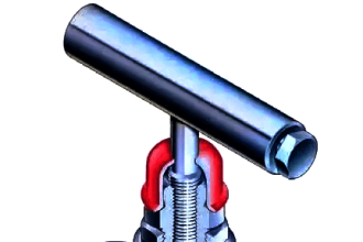
The backlash can be measured with dial gauge, feeler gauge or lead wire. The Dial Gauge pointer is kept at Driven gear face and the drive gear is locked. Then the driven gear is moved which shows the backlash valve in the dial gauge.

Gear box backlash

What is Gear Box Backlash

Another Method is keeping the lead wire in between the two faces of the mating gear and allowed to mesh.

After the lead wire compresses, it is measured with the micrometer which shows the backlash reading.

Reasons for Gear Backlash increase

  • Due to gear face wear after running so many hours
  • Due to bearing Radial wear
  • If the center distance between two gear is high

Back Lash and Gear box Clearance are different. Gearbox clearance is the space between the addendum circle of one gear to the deddendum circle of another gear

Backlash valve for normal gearbox 0.18-0.3mm for heavy load < 3mm

There should be sufficient backlash for allowing lubrication to gears and compensate mis-alignments.

Don't Miss Our Updates
Be the first to get exclusive content straight to your email.
We promise not to spam you. You can unsubscribe at any time.
Invalid email address
You've successfully subscribed !

Continue Reading

What is Turbine Supervisory Instrumentation (TSI)?
Gas Turbine Interview Questions and Answers
What is an Air Pre-heater? – Types, Working, Advantages
Turbine Control System
Thermal Power Plant – Basic Layout, Parts, Principle
Process and Mechanical Parameters in Steam Turbine
Share This Article
Facebook Whatsapp Whatsapp LinkedIn Copy Link
Share
Leave a Comment

Leave a Reply Cancel reply

Your email address will not be published. Required fields are marked *

Stay Connected

128.3kFollowersLike
69.1kFollowersFollow
210kSubscribersSubscribe
38kFollowersFollow

Categories

Explore More

What are the Interlocks for Steam Turbine?
Parts and functions of Steam Turbine
Classification of Steam Turbines
Gas Turbine Control System
Boiler Safety and Process Interlocks – Power Plant Tutorials
Measurement of Impurities in Water and Steam – Power Plant
Gas Turbine Troubleshooting Tips
Different Types of Turbine Protective Devices

Keep Learning

Economizer

What is an Economizer? Purpose, Classification, Advantages

What is Gear Run Out

What is Gear Run Out ?

What is Barring Gear Logic? Why is it Required in the Steam Turbine?

Thermodynamic cycle

Thermodynamic Cycles in Power Plant

30% Feed Control Valve

Purpose of 100% and 30% Feed Control Valves in a Power Plant

Turbine and Compressor Control System

Turbine and Compressor Control System

Single Phase Energy Meter

Measurement of Electrical Parameters in Steam Turbine

Furnace Draft Control System

Furnace Draft Control System

Learn More

Dahlander Motor Control Circuit

Dahlander Motor Control Circuit and Power Circuit

Flare KOD

Flare Knockout Drums Working Animation

Time Response Analysis

Robotic Control System – Part I

Electrical Machines Questions and Answers

Energy Conversion Quiz

3 Way Circuit Animation

Three Way Electrical Switch Working Animation

Rotary Granulator Drive

Rotary Granulator Drive Root Cause Analysis (RCA)

Transmitter Indicators

What is Indicator ?

Purpose of Stop in a Pressure Measuring Instrument

Purpose of Stop in a Pressure Measuring Instrument

Menu

  • About
  • Privacy Policy
  • Copyright

Quick Links

  • Learn PLC
  • Helping Hand
  • Part Time Job

YouTube Subscribe

Follow US
All rights reserved. Reproduction in whole or in part without written permission is prohibited.
Welcome Back!

Sign in to your account

Username or Email Address
Password

Lost your password?