Inst ToolsInst ToolsInst Tools
  • Courses
  • Automation
    • PLC
    • Control System
    • Safety System
    • Communication
    • Fire & Gas System
  • Instrumentation
    • Design
    • Pressure
    • Temperature
    • Flow
    • Level
    • Vibration
    • Analyzer
    • Control Valve
    • Switch
    • Calibration
    • Erection & Commissioning
  • Interview
    • Instrumentation
    • Electrical
    • Electronics
    • Practical
  • Q&A
    • Instrumentation
    • Control System
    • Electrical
    • Electronics
    • Analog Electronics
    • Digital Electronics
    • Power Electronics
    • Microprocessor
  • Request
Search
  • Books
  • Software
  • Projects
  • Process
  • Tools
  • Basics
  • Formula
  • Power Plant
  • Root Cause Analysis
  • Electrical Basics
  • Animation
  • Standards
  • 4-20 mA Course
  • Siemens PLC Course
Reading: Full Wave Rectifier
Share
Font ResizerAa
Inst ToolsInst Tools
Font ResizerAa
  • Courses
  • Design
  • PLC
  • Interview
  • Control System
Search
  • Courses
  • Automation
    • PLC
    • Control System
    • Safety System
    • Communication
    • Fire & Gas System
  • Instrumentation
    • Design
    • Pressure
    • Temperature
    • Flow
    • Level
    • Vibration
    • Analyzer
    • Control Valve
    • Switch
    • Calibration
    • Erection & Commissioning
  • Interview
    • Instrumentation
    • Electrical
    • Electronics
    • Practical
  • Q&A
    • Instrumentation
    • Control System
    • Electrical
    • Electronics
    • Analog Electronics
    • Digital Electronics
    • Power Electronics
    • Microprocessor
  • Request
Follow US
All rights reserved. Reproduction in whole or in part without written permission is prohibited.
Inst Tools > Blog > Electronic Devices & Circuits > Full Wave Rectifier

Full Wave Rectifier

Last updated: October 4, 2016 12:29 pm
Editorial Staff
Electronic Devices & Circuits
No Comments
Share
1 Min Read
SHARE

A full-wave rectifier allows unidirectional (one-way) current through the load during the entire 360° of the input cycle, whereas a half-wave rectifier allows current through the load only during one-half of the cycle. The result of full-wave rectification is an output voltage with a frequency twice the input frequency and that pulsates every half-cycle of the input.

Full Wave Rectifier

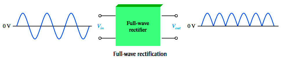
The number of positive alternations that make up the full-wave rectified voltage is twice that of the half-wave voltage for the same time interval. The average value, which is the value measured on a dc voltmeter, for a full-wave rectified sinusoidal voltage is twice that of the half-wave, as shown in the following formula:

full-wave-rectifier-equation


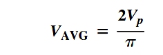
VAVG is approximately 63.7% of Vp for a full-wave rectified voltage.

Types of Full Wave Rectifier

  1. Center Tapped Full Wave Rectifier
  2. Bridge Full Wave Rectifier

Note : Click on above links to read full articles on rectifiers.

Don't Miss Our Updates
Be the first to get exclusive content straight to your email.
We promise not to spam you. You can unsubscribe at any time.
Invalid email address
You've successfully subscribed !

Continue Reading

How a PN Junction Formed in a Diode
Combining Independent Voltage Sources in Series
Optocouplers Working Principle
Transistor Emitter Feedback Bias
Photodiode Working Principle
Phototransistor Working Principle
Share This Article
Facebook Whatsapp Whatsapp LinkedIn Copy Link
Share
Leave a Comment

Leave a Reply Cancel reply

Your email address will not be published. Required fields are marked *

Stay Connected

128.3kFollowersLike
69.1kFollowersFollow
210kSubscribersSubscribe
38kFollowersFollow

Categories

Explore More

Energy Diagrams of PN Junction & Depletion Region
PMMC Temperature Compensation
Methods of Transistor Biasing
Band Gap for Semiconductor Materials
CRT Fluorescent Screen
Comparison of Half wave Rectifiers and Full wave Rectifiers
Transistor Cut off, Saturation & Active Regions
Types of Resistors

Keep Learning

Permanent magnet moving coil instruments (PMMC)

Permanent Magnet Moving Coil Instruments (PMMC)

diode-clamper-circuit

Diode Clampers Principle

parallel-resistors-circuit-example

Series and Parallel Resistors

Tunnel Diode

Tunnel Diode Working Principle

Transistor as an Amplifier in Common Emitter

Transistor as an Amplifier in Common Emitter

capacitor-filter-ripples

Ripple Voltage in Rectifiers

Diode-positive-limiter

Positive & Negative Diode Clippers

What is a Memristor

What is a Memristor? Principle, Advantages, Applications

Learn More

Reed Switch Principle

Reed switch Working Principle

Dataloggers Objective Questions

Data Loggers Objective Questions

Keyphasor Principle

What is Keyphasor ? How does Keyphasor works ?

Power Electronics Objective Questions

Choppers Multiple Choice Questions

Sample of a production Downtime

How to Use Production Line Failures for Your Gains?

Pressure Gauges with Zero Adjustment

Pressure Gauges Zero Adjustment

Types of Circuit Breakers

Types of Circuit Breakers, Advantages, Disadvantages

Time Response Analysis

Effect of Adding a Zero to a System – II

Menu

  • About
  • Privacy Policy
  • Copyright

Quick Links

  • Learn PLC
  • Helping Hand
  • Part Time Job

YouTube Subscribe

Follow US
All rights reserved. Reproduction in whole or in part without written permission is prohibited.
Welcome Back!

Sign in to your account

Username or Email Address
Password

Lost your password?