Inst ToolsInst ToolsInst Tools
  • Courses
  • Automation
    • PLC
    • Control System
    • Safety System
    • Communication
    • Fire & Gas System
  • Instrumentation
    • Design
    • Pressure
    • Temperature
    • Flow
    • Level
    • Vibration
    • Analyzer
    • Control Valve
    • Switch
    • Calibration
    • Erection & Commissioning
  • Interview
    • Instrumentation
    • Electrical
    • Electronics
    • Practical
  • Q&A
    • Instrumentation
    • Control System
    • Electrical
    • Electronics
    • Analog Electronics
    • Digital Electronics
    • Power Electronics
    • Microprocessor
  • Request
Search
  • Books
  • Software
  • Projects
  • Process
  • Tools
  • Basics
  • Formula
  • Power Plant
  • Root Cause Analysis
  • Electrical Basics
  • Animation
  • Standards
  • 4-20 mA Course
  • Siemens PLC Course
Reading: Four Electrode Conductivity Probes Principle
Share
Font ResizerAa
Inst ToolsInst Tools
Font ResizerAa
  • Courses
  • Design
  • PLC
  • Interview
  • Control System
Search
  • Courses
  • Automation
    • PLC
    • Control System
    • Safety System
    • Communication
    • Fire & Gas System
  • Instrumentation
    • Design
    • Pressure
    • Temperature
    • Flow
    • Level
    • Vibration
    • Analyzer
    • Control Valve
    • Switch
    • Calibration
    • Erection & Commissioning
  • Interview
    • Instrumentation
    • Electrical
    • Electronics
    • Practical
  • Q&A
    • Instrumentation
    • Control System
    • Electrical
    • Electronics
    • Analog Electronics
    • Digital Electronics
    • Power Electronics
    • Microprocessor
  • Request
Follow US
All rights reserved. Reproduction in whole or in part without written permission is prohibited.
Inst Tools > Blog > Analyzers > Four Electrode Conductivity Probes Principle

Four Electrode Conductivity Probes Principle

Last updated: August 31, 2018 9:31 pm
Editorial Staff
Analyzers
No Comments
Share
4 Min Read
SHARE

A very old electrical technique known as the Kelvin or four-wire resistance-measuring method is a practical solution to the problem of electrode fouling faced by two-electrode conductivity probes. Commonly employed to make precise resistance measurements for scientific experiments in laboratory conditions, as well as measuring the electrical resistance of strain gauges and other resistive sensors such as RTDs, the four-wire technique uses four conductors to connect the resistance under test to the measuring instrument:

Four Electrode Conductivity Probes Principle

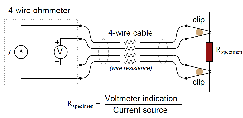
Only the outer two conductors carry substantial current. The inner two conductors connecting the voltmeter to the test specimen carry negligible current (due to the voltmeter’s extremely high input impedance) and therefore drop negligible voltage along their lengths. Voltage dropped across the current-carrying (outer) wires is irrelevant, since that voltage drop is never detected by the voltmeter.

Since the voltmeter only measures voltage dropped across the specimen (the resistor under test), and not the test resistance plus wiring resistance, the resulting resistance measurement is much more accurate than if only two wires were used to connect the test meters to the specimen.

In the case of conductivity measurement, it is not wire resistance that we care to ignore, but rather the added resistance caused by fouling of the electrodes. By using four electrodes instead of two, we are able to measure voltage dropped across a length of liquid solution only, and completely ignore the resistive effects of electrode fouling:

conductivity measurement Theory

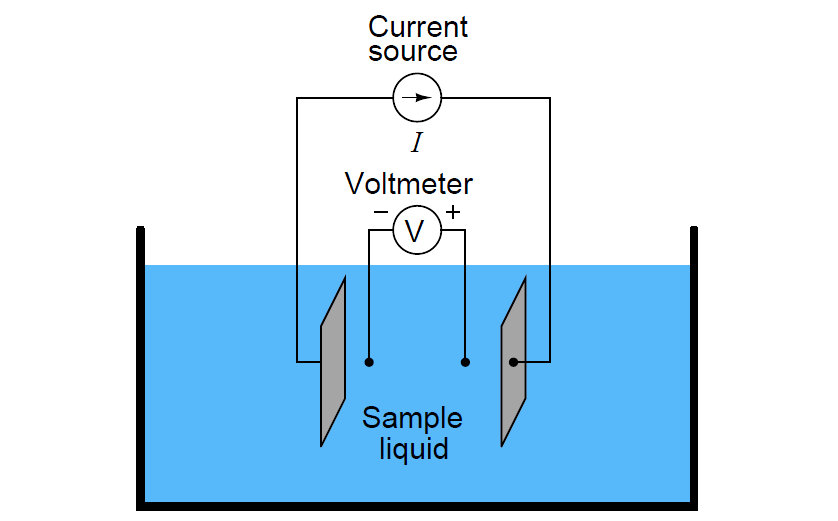
In the 4-wire conductivity cell, any electrode fouling will merely burden the current source by causing it to output a greater voltage, but it will not affect the amount of voltage detected by the two inner electrodes as that electric current passes through the liquid. Any fouling that happens to occur on the two inner electrodes is of no effect to our conductivity measurement because these inner electrodes carry negligible current. With little or no current through the inner electrodes, there will be negligible voltage dropped across any resistive coating that happens to form on them, and thus the voltmeter will still register the true voltage dropped by the liquid solution.

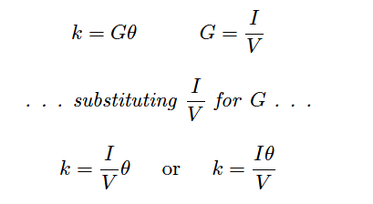
If the solution’s conductivity is defined as the product of the measured conductance and the cell constant (k = Gθ), and conductance is defined as the ratio of current to voltage (G = I/V ), then we may determine conductivity from voltage and current measurements by combining these two equations:

Four Electrode Conductivity Probes Formula

Some conductivity instruments employ a second voltmeter to measure the voltage dropped between the “excitation” electrodes, to indicate electrode fouling:

conductivity instruments

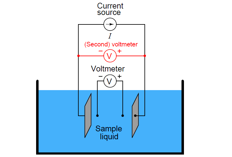
Any form of electrode fouling will cause this secondary voltage measurement to disproportionately exceed the first, thus providing an indicator that instrument technicians may use for predictive maintenance (telling them when the probes need cleaning or replacement). Meanwhile, the primary voltmeter will do its job of accurately measuring liquid conductivity so long as the current source is still able to output its normal amount of current.

Also Read : Toroidal Conductivity Sensors Principle

Don't Miss Our Updates
Be the first to get exclusive content straight to your email.
We promise not to spam you. You can unsubscribe at any time.
Invalid email address
You've successfully subscribed !

Continue Reading

Humidity calculator
Working Principle of Gas chromatograph
Dissolved Oxygen Analyzer Interview Questions & Answers
Sodium Analyzer Problems and Troubleshooting Steps
Luft detector Principle
Turbidity Sensor Calibration Procedure
Share This Article
Facebook Whatsapp Whatsapp LinkedIn Copy Link
Share
Leave a Comment

Leave a Reply Cancel reply

Your email address will not be published. Required fields are marked *

Stay Connected

128.3kFollowersLike
69.1kFollowersFollow
210kSubscribersSubscribe
38kFollowersFollow

Categories

Explore More

Hydrazine Analyzer Working Principle
Industrial Applications of Chromatographs
Top 100 Analytical Instrumentation Engineering Projects
Thermal Conductivity Detector (TCD) Principle
Conductivity Measurement
Dual-beam Non-dispersive Analyzer
Electrodeless Conductivity Probes Principle
Dissolved oxygen probe calibration procedure

Keep Learning

pH Analyzer Do’s and Don’ts

pH Analyzer Do’s and Don’ts

Ph Meter Principle

pH measurement

Infrared Flue Gas Analyser

What is Infrared Flue Gas Analyzer? – Working Principle

Moisture Calculator

Moisture Calculator

Turbidity Analyzer Working Principle

Turbidity Analyzer Working Principle

Two Electrode Conductivity Probes

Two Electrode Conductivity Probes Principle

process chemical analyzer calibration

Automated Calibration

online silica analyzer

Silica Analyzer Problems and Troubleshooting Tips

Learn More

Siemens LOGO PLC Complete Programming Course

Siemens LOGO PLC Complete Programming Course

Accuracy of a Manometer

What Affect the Pressure Measurement Accuracy of a Manometer?

Modern Cement Kiln Drive

Cement kilns, Rotary Drum Driers Simplest Electrical Drive

What are Fire Branches?

What are Fire Branches?

Measurement and Calibration Objective Questions and Answers

Measurement and Calibration Objective Questions

V1000 Family Programming Simulator Tool

VFD Simulator Download – Free Yaskawa V1000 Software

Control Panel Instruments

Control Panel Instruments Problem Threatened Plant Shutdown

Reed Switch Principle

Reed switch Working Principle

Menu

  • About
  • Privacy Policy
  • Copyright

Quick Links

  • Learn PLC
  • Helping Hand
  • Part Time Job

YouTube Subscribe

Follow US
All rights reserved. Reproduction in whole or in part without written permission is prohibited.
Welcome Back!

Sign in to your account

Username or Email Address
Password

Lost your password?