Inst ToolsInst ToolsInst Tools
  • Courses
  • Automation
    • PLC
    • Control System
    • Safety System
    • Communication
    • Fire & Gas System
  • Instrumentation
    • Design
    • Pressure
    • Temperature
    • Flow
    • Level
    • Vibration
    • Analyzer
    • Control Valve
    • Switch
    • Calibration
    • Erection & Commissioning
  • Interview
    • Instrumentation
    • Electrical
    • Electronics
    • Practical
  • Q&A
    • Instrumentation
    • Control System
    • Electrical
    • Electronics
    • Analog Electronics
    • Digital Electronics
    • Power Electronics
    • Microprocessor
  • Request
Search
  • Books
  • Software
  • Projects
  • Process
  • Tools
  • Basics
  • Formula
  • Power Plant
  • Root Cause Analysis
  • Electrical Basics
  • Animation
  • Standards
  • 4-20 mA Course
  • Siemens PLC Course
Reading: FMCW Radar Level Transmitter Working Principle
Share
Font ResizerAa
Inst ToolsInst Tools
Font ResizerAa
  • Courses
  • Design
  • PLC
  • Interview
  • Control System
Search
  • Courses
  • Automation
    • PLC
    • Control System
    • Safety System
    • Communication
    • Fire & Gas System
  • Instrumentation
    • Design
    • Pressure
    • Temperature
    • Flow
    • Level
    • Vibration
    • Analyzer
    • Control Valve
    • Switch
    • Calibration
    • Erection & Commissioning
  • Interview
    • Instrumentation
    • Electrical
    • Electronics
    • Practical
  • Q&A
    • Instrumentation
    • Control System
    • Electrical
    • Electronics
    • Analog Electronics
    • Digital Electronics
    • Power Electronics
    • Microprocessor
  • Request
Follow US
All rights reserved. Reproduction in whole or in part without written permission is prohibited.
Inst Tools > Blog > Level Measurement > FMCW Radar Level Transmitter Working Principle

FMCW Radar Level Transmitter Working Principle

Last updated: December 2, 2019 3:34 pm
Editorial Staff
Level Measurement
1 Comment
Share
2 Min Read
SHARE

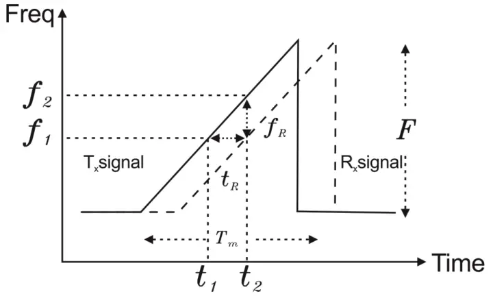
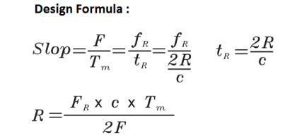
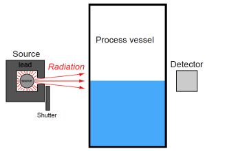
A radar signal is emitted via an antenna, reflected on the product surface and received after a time t. The radar principle used is FMCW (Frequency Modulated Continuous Wave). The FMCW-radar transmits a high frequency signal whose frequency increases linearly during the measurement phase (called the frequency sweep).

The signal is emitted, reflected from the measuring surface and received with a time delay, t. Delay time, t=2d/c, where d is the distance to the product surface and c is the speed of light in the gas above the product.

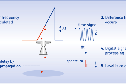
For further signal processing the difference Δf is calculated from the actual transmit frequency and the receive frequency. The difference is directly proportional to the distance. A large frequency difference corresponds to a large distance and vice versa.

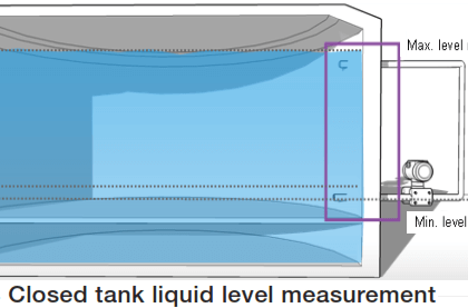
The frequency difference Δf is transformed via a Fourier transformation (FFT) into a frequency spectrum and then the distance is calculated from the spectrum. The level results from the difference between tank height and measuring distance.

FMCW Radar level transmitter Working Principle

The frequency difference that is processed by Fast Fourier Transformation (FFT) to identify the signal in Intermedium Frequency (IF). This FMCW radar is innate with signal / noise enhancement and filtering of echo-back via Phase-Lock Loop (PLL) circuit that is the best solution for complex environment and high accuracy measurement.

Radar Level Transmitter Formula

source : FineTek/Krohne

Don't Miss Our Updates
Be the first to get exclusive content straight to your email.
We promise not to spam you. You can unsubscribe at any time.
Invalid email address
You've successfully subscribed !

Continue Reading

Radar Level Transmitter in Briddle level Measurement
Non-Contacting Radar Level Transmitter Working Principle
Differential Pressure Transmitters Compensated Leg Systems
What is Dip Tape Level Measurement?
RF Level Switches Working Principle
How to do Interface Level Calculation using DP Transmitter ?
Share This Article
Facebook Whatsapp Whatsapp LinkedIn Copy Link
Share
1 Comment
  • Kyp Durron says:
    January 4, 2017 at 5:13 am

    I tink you could improve this article is at least incomplete, regards.

    Reply

Leave a Reply Cancel reply

Your email address will not be published. Required fields are marked *

Stay Connected

128.3kFollowersLike
69.1kFollowersFollow
210kSubscribersSubscribe
38kFollowersFollow

Categories

Explore More

DP Level Transmitter with Zero Suppression Calibration
Air Purge or Air Bubbler Level Measurement
Manual Level Measurement
What is Thermal Differential Level Measurement?
Differential Pressure (DP) Level transmitter Installed Below Tapping Point
Siemens Differential Pressure Transmitter Calculations (Flange Type)
what is a Bubbler System?
Level Calculation with Remote Seals

Keep Learning

Difference between Transparent Level Gauge and Reflex Level Gauge

Difference between Transparent Level Gauge and Reflex Level Gauge

Level Transmitter with Zero Suppression

DP Level Transmitters Compensation Techniques

Boiler Three Element Controller Philosophy

Boiler Three Element Controller Philosophy

Which instrument is at fault in this system

Which Instrument is at Fault in this System?

Ultrasonic Transmitters vs. Guided Wave Radar Transmitters

Ultrasonic Transmitters vs Guided Wave Radar for Level Measurement

level gauge

Basics of Sight Glass Level Gauge

Bubbler Level Measurement Animation

Bubbler Level Measurement Animation

Stilling wells

Stilling Wells for Level Measurement

Learn More

Solenoid Valves Questions

Solenoid Valves Questions & Answers – 3

Closed-Tank-DP-Type-Level-Measurement-with-Dry-leg-and-transmitter-installed-below-tapping-point

Level Measurement with Dry leg and Installed Below Tapping Point

Best Software to Use to Improve Your Business

Best Software to Use in 2023 to Help Improve the Effectiveness of Your Business

Electronic Devices & Circuits Objective Questions

Electronic Devices & Circuits Quiz – Set 14

Hybrid Level Transmitter Principle

Hybrid Level Measurement Principle, Selection, Installation, Limitations and Calibration

Level Transmitter with Zero Suppression

DP Level Transmitters Compensation Techniques

Electrical Power Grid Automation

Electrical Power Grid Automation

PLC Automatic Pedal Switch for Speed Control

PLC Automatic Pedal Switch for Speed Control

Menu

  • About
  • Privacy Policy
  • Copyright

Quick Links

  • Learn PLC
  • Helping Hand
  • Part Time Job

YouTube Subscribe

Follow US
All rights reserved. Reproduction in whole or in part without written permission is prohibited.
Welcome Back!

Sign in to your account

Username or Email Address
Password

Lost your password?