Inst ToolsInst ToolsInst Tools
  • Courses
  • Automation
    • PLC
    • Control System
    • Safety System
    • Communication
    • Fire & Gas System
  • Instrumentation
    • Design
    • Pressure
    • Temperature
    • Flow
    • Level
    • Vibration
    • Analyzer
    • Control Valve
    • Switch
    • Calibration
    • Erection & Commissioning
  • Interview
    • Instrumentation
    • Electrical
    • Electronics
    • Practical
  • Q&A
    • Instrumentation
    • Control System
    • Electrical
    • Electronics
    • Analog Electronics
    • Digital Electronics
    • Power Electronics
    • Microprocessor
  • Request
Search
  • Books
  • Software
  • Projects
  • Process
  • Tools
  • Basics
  • Formula
  • Power Plant
  • Root Cause Analysis
  • Electrical Basics
  • Animation
  • Standards
  • 4-20 mA Course
  • Siemens PLC Course
Reading: Float & Dial Level Gauge Principle
Share
Font ResizerAa
Inst ToolsInst Tools
Font ResizerAa
  • Courses
  • Design
  • PLC
  • Interview
  • Control System
Search
  • Courses
  • Automation
    • PLC
    • Control System
    • Safety System
    • Communication
    • Fire & Gas System
  • Instrumentation
    • Design
    • Pressure
    • Temperature
    • Flow
    • Level
    • Vibration
    • Analyzer
    • Control Valve
    • Switch
    • Calibration
    • Erection & Commissioning
  • Interview
    • Instrumentation
    • Electrical
    • Electronics
    • Practical
  • Q&A
    • Instrumentation
    • Control System
    • Electrical
    • Electronics
    • Analog Electronics
    • Digital Electronics
    • Power Electronics
    • Microprocessor
  • Request
Follow US
All rights reserved. Reproduction in whole or in part without written permission is prohibited.
Inst Tools > Blog > Level Measurement > Float & Dial Level Gauge Principle

Float & Dial Level Gauge Principle

Last updated: October 30, 2019 12:37 pm
Editorial Staff
Level Measurement
No Comments
Share
2 Min Read
SHARE

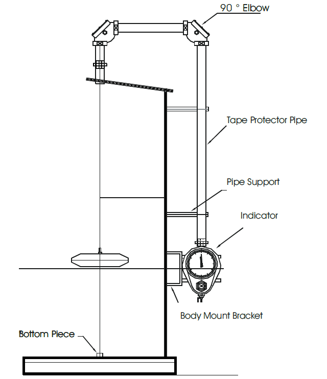
The tank level indicators are of simple construction and are easy to install. They are very sturdy and require no maintenance. A float operated tank indicator comprises of a float that is located within guide cables. The guide cables whose ends are fastened on to an anchor bar are kept straight and wrinkle free by tension devices.

Float & Dial Level Gauge Principle

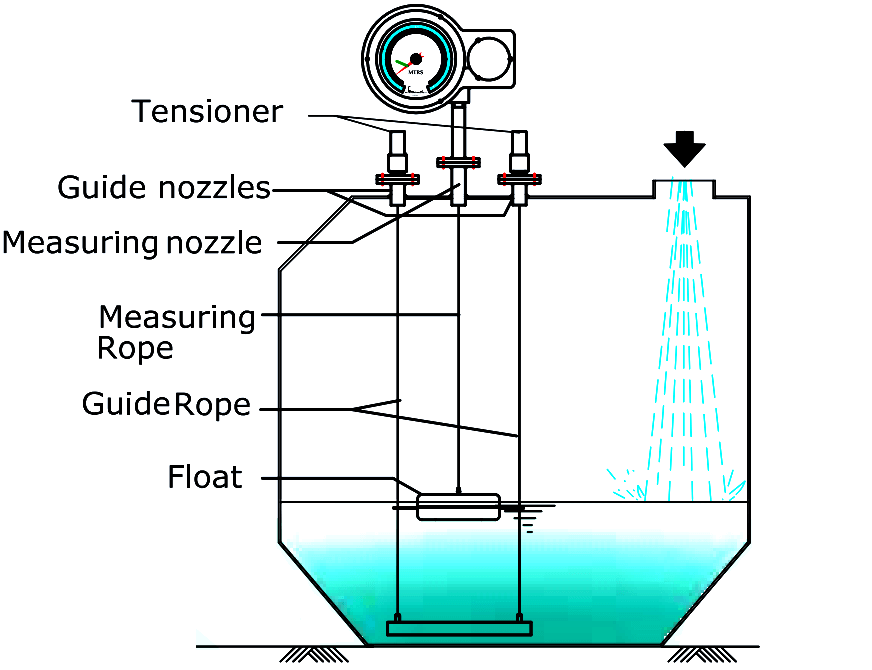
The anchor bar is either grouted or welded to the tank bases. The float cable is wound over a set of pulleys, which are secured in the pulley housing. One end of the float cable bears the float and the other end carries a pointer assembly with a counter weight for balance. Tank level indicator float operated type is for fixed roof, floating roof, open top and under ground storage tanks.
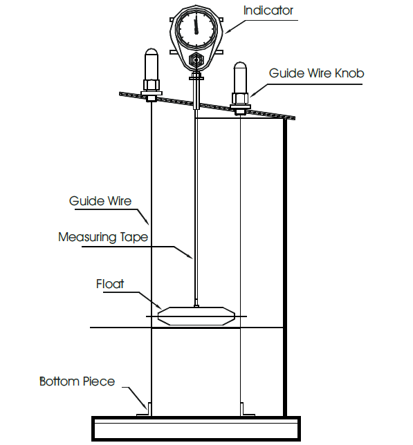
Principle :

It consists of a float, tied to a SS wire rope, other side of which is wound on a drum carrying constant torque spring, to maintain the rope under continuous tension. Due to change in liquid level the float rises or falls and rotates the drum. This motion is transmitted thru gear mechanism to a pointer moving over a calibrated dial to display level in meters, Digital / Analogue output can also be provided for Switching & Transmitting as an option.

Installation on Top of the Tank :

Tank Float Level Indicator

Installation on the Tank side :

Tank Level Indicator using Float

Don't Miss Our Updates
Be the first to get exclusive content straight to your email.
We promise not to spam you. You can unsubscribe at any time.
Invalid email address
You've successfully subscribed !

Continue Reading

Differential Pressure Transmitters Compensated Leg Systems
Paddle Wheel Level Switch Principle
What is a Level Switch? Types of Level Switches
Capacitance Level Switch Working Principle
Radar Level Transmitter in Briddle level Measurement
Ultrasonic Level Switch Principle
Share This Article
Facebook Whatsapp Whatsapp LinkedIn Copy Link
Share
Leave a Comment

Leave a Reply Cancel reply

Your email address will not be published. Required fields are marked *

Stay Connected

128.3kFollowersLike
69.1kFollowersFollow
210kSubscribersSubscribe
38kFollowersFollow

Categories

Explore More

How to Find LRV and URV of Closed Tank DP Level Transmitter
All About Instrumentation Impulse Lines
Tank Level Detection Switches
How a Level Switch Works
What is Displacer Level Sensor ?
Ultrasonic Level Transmitter Working Principle
Open Tank Level Measurement using DP Transmitter
Closed Tank Level Measurement using DP Transmitters

Keep Learning

Dip Tape

What is Dip Tape Level Measurement?

How to Install Ultrasonic Level Transmitters 5

How to Install Ultrasonic Level Transmitters

Two pressure transmitters

Pressure Transmitters Leg Compensation Technique

Ultrasonic-Level-Transmitter-Animation

Ultrasonic Level Transmitter Animation

Tank Gauging Measurement

Purpose of Tank Gauging Level Measurement

Radar and Ultrasonic Level Transmitter Problems Troubleshooting

Radar and Ultrasonic Level Transmitter Practical Problems Troubleshooting

Bubbler Level Measurement System

Bubbler Level Sensor

Level Measurement Objective Questions

Level Measurement Objective Questions

Learn More

Time Response Analysis

Effect of Adding a Zero to a System – II

Power Electronics Objective Questions

Thyristor Family Quiz

CNC Machining Glass Industry

5 Ways CNC Machining is Benefiting the Glass Industry

WirelessHART mesh network

WirelessHART

Resistor-Color-Code-Chart

Resistor Color Code Animation

Advanced Process Control

What is Advanced Process Control (APC)?

Chemical Dosing Control System

Introduction to Chemical Dosing System

Power Electronics Objective Questions

Three-Phase Rectifier Quiz

Menu

  • About
  • Privacy Policy
  • Copyright

Quick Links

  • Learn PLC
  • Helping Hand
  • Part Time Job

YouTube Subscribe

Follow US
All rights reserved. Reproduction in whole or in part without written permission is prohibited.
Welcome Back!

Sign in to your account

Username or Email Address
Password

Lost your password?