Instrumentation engineering root cause analysis (RCA) of fire burnt ammonia converter thermocouple (TC) problem threaten entire plant shutdown.
| Article Type: | Root Cause Analysis (RCA) |
| Category: | Instrumentation |
| Equipment Type: | Sensors |
| Author: | S. Raghava Chari |
Note: This root cause analysis (RCA) is from real-time scenarios that happened in industries during the tenure of two or three decades ago. These articles will help you to improve your troubleshooting skills and knowledge.
NH3 Convertor Catalyst Beds Temperature Measuring System 750‑1500 T/d NH3 convertors are 1.2 to 1.8 m dia x 20 m tall vessels operating at 220 bars 430o C. 24 Mineral Insulated Duplex Chromel-Alumel Thermocouples (MITC) measure the 3 catalyst beds temperatures.
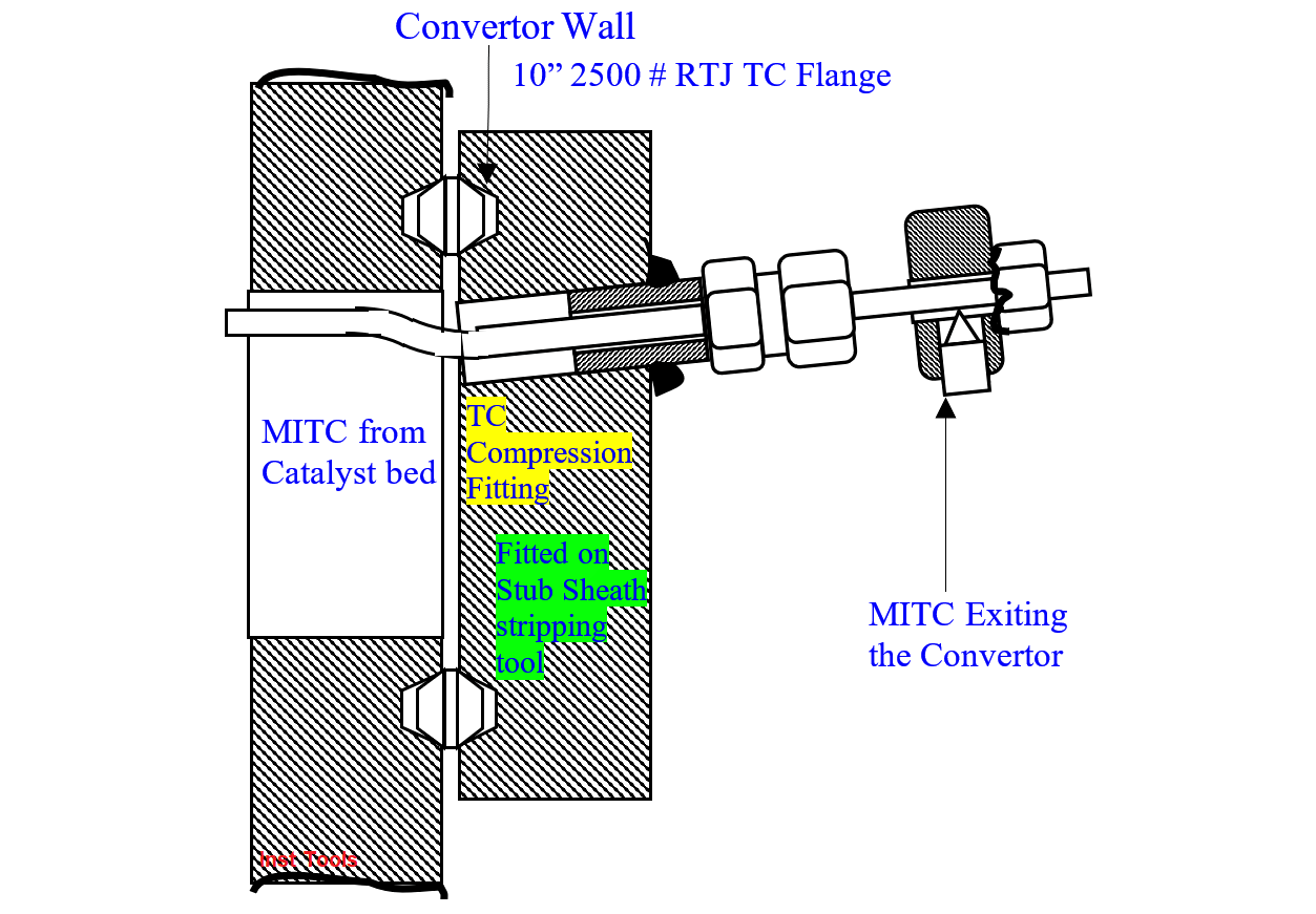
From now on MITC means duplex MITC for this article. Convertor external crew insert each MITC into the convertor via compression fittings – one for each MITC – welded to the 10” 2500 # RTJ thermocouple flange (TCF, fig 1) bolted to the convertor shell near top.
This avoids welding 24 thermowell taps on this 220 bars 450o C operating high pressure vessel subjected to severe welding codes.
Consider catalyst bed 3 (CB3) corner 1 top temp measurement: A 3/8” Sch 80 bottom end closed and adequately supported incolloy pipe (IP) extends from Thermocouple Flange (TCF, Fig 1) bottom level up to the CB3 top layer.
Convertor inside crew inserts it into the IP till it bottoms. Thus, the IP guards the TC as process thermowells do. IP end cut 4 Nos. 2.5 wide x 30 mm long slots allow the process gas to wet the MITC sheath for enhanced temp measurement sensitivity.
Thus 8-Nos. MITCs measure each beds’ 4‑corners top and bottom temperatures, and total 24 MITCs installed as above the 3-beds. Convertor outside crew terminates the 24 MITCs’ color-coded leads at the terminals of the Thermocouple Junction Box (TCJB) bolted to a pillar 3-m away.
Operators load the 3-beds’ catalysts after the instrument crews complete the TC installation, check, and give catalyst load clearance.
After 3 years good run, the plant professional fire fighters, trained volunteer fire fighters and others put out the huge fire noticed at the TCF. After fire quench checks identified that Synthesis Gas leaks at the TCF and CFs caused the fire.
This fire burnt the 24‑Nos MITCs and left 100 to 200 mm long stubs at TCF, and 50 m of the 110 m long Extension Lead cable (ELC) connecting the MITCs to the panel Temperature Recorder (TR) and the backup Temperature Indicator (TI).
A German physicist Thomas Seebeck found heating a long homogeneous composition of few metals or alloys wire types generates few mV potential difference aka electromotive force (EMF) between the wire’s ends.
In fig 2, heating wire W1 right end increase its left end mV higher than the right end’s. Using this principle, thermocouple makers make e.g., a PtRh-Pt thermocouple (TC, fig 2) to measure, e.g., molten steel temp in a ladle.
PtRh wire is the +ve thermocouple wire; it generates tabled mV at different temperatures. The negative Pt wire generating much lower mVs than the PtRh-Pt wire for a given ∆t helps connecting the +ve wire hot end to the voltmeter -ve terminal. Note both TC wires shall withstand the process temp.
The +ve wire generates max mV for the measured temp and the -ve wire the least mV to maximize the temperature measurement sensitivity. Thus, two dissimilar wires W1 and W2 combination as in fig 2 constitutes a Thermocouple (TC).
It produces an emf at the TC head (TCH) terminals depending on the temperature difference between the Measuring Junction (M) and the TCH terminals. Usually, the TCH’s all terminals would be at the same temperature – a requirement for the TCs max accuracy.
If we connect the head terminals to the remote panel temp indicator (TI), by means of copper wires, industries usual wires, the TI terminals mV = k(TM – TH).
The terminals where the TC wires end e.g., TC head (fig 3). The environs and too close to the furnace/equipment wall situated TH varies considerably within a day and seasonally.
Hence, instead of the copper wires, wires called Extension Leads (EL) connect TCH to e.g., panel TI terminals. EL wires are of less expensive metals/alloys, and have the same thermoelectric properties as TC wires up to 200o C. Obviously, EL wires need not withstand the high process temperatures.
Note TC’s Law of Intermediate Materials validates different metals’ use in fig 3 and 16 TC circuits. The law says “Different metals addition to a TC circuit does not alter the TC generated EMFs, if the connected terminals have the same temperature.
In fig, the TC + and -ve wires connect to head brass terminals, (all different metal / alloys). If the head terminals and connecting wire ends temp are the same the TC generated emf remains the same at (TM‑TH).
Putting the warehouse held 24 nos. MITC set was impossible because:
Hence, the author trusting in God and his crew attempted restoring the temperature readings by joining the TCF stubs to the 3 m away TCJB hook or crook.
Below are the faced constraints
An instrument technician wiped the fire quench left water and epoxy sealed to prevent the stubs MgO insulation absorbed moisture shorting the TC wires and rendering them useless immediately after fire quench.
An instrument technician and an electrician team removed the fire burnt MITC lengths from TCF to TCJB piled them neatly for any likely uses. They ran EL lengths from the TCJB and tagged the TC No. on each extension lead cable (ELC) at the TCF end.
The author trained four teams – each of an electrician and an instrument technician, a team for each 8‑hrs shift and one standby in case of absence as abundant caution. This leaves enough instrument technicians for the complex’s other needs.
A millwright tightened the TC flange studs, and an instrument technician the CFs – both soap bubble test leaks free. Too often slipped spanner falls, its recovery descends to the 20 m below floor and ascends slowed the CF tightening task ridiculously.
The author twine tying the spanner to the grill speeded up the task beyond expectations, besides preventing persons around injuries.
The convertor still under 100-bars, 200O C, syn Gas pressure enabled leak testing and tightening the TCF studs, and the CFs leak tight.
A ‘graduate’ team set to join the stub TC wires to JB1 terminated extension lead wires thus:
Other crews completed rest of the connections – see next problem -, the converter was ready for use in just 5 days, and the threatened high-cost catalyst loss and indefinite total plant outage threats disappeared.
The Indian Managing Director hailed this feat telling “Raghav, I repeat EPW’s (E.P. Wells former US GM) words after you recovered the burst pipe destroyed panel instrumentation, “you and your team have reconstructed truck crushed 22 out of 24 eggs”.
The Temp Readings Restoration Benefits are:
The author now the maintenance manager completed the below pre-SD arrangements to change the unacceptable activity convertor catalyst 15 years after this incident:
Thanks to the well-done and tried out arrangements, the US firm’s technicians using life support systems entered the shutdown (SD) and cooled to 30o C and 10 mm WC inert gas pressured convertor and evacuated the 20 years old spent catalysts in 3-days, perhaps the first time in India.
Conventional methods would have taken 21 days and consumed 100 times more Inert Gas injected with controlled increasing air quantities to fully oxidize the catalyst and evacuate it manually. Problems like lumped up catalysts if any would have extended the evacuation times up to 50% even!
The instrument team put the spare MITCs and terminated them on the field junction box in one day after catalyst evacuation.
The operations and tech services crew loaded 25 tons got from Denmark, pre-reduced, but skin oxidized catalysts in 5 days. Pre-reduction eliminates 21-days reduction times after charging, enormous N2, H2 mixture quantities use and skin oxidation prevents fires during catalyst loading.
An assigned instrument technician ensured the catalyst loaders NOT DAMAGING the MITCs during the five loading days, as replacing damaged TCs is near impossible even catalyst partially loaded, and these must work fine during the new catalyst’s > 20 years expected lives.
This and the other case studies show how instrumentation ties so closely with the plants’ overall activities. Hence, instrument engineers must not only enhance instrumentation knowledge but also increase their overall plant knowledge.
This will not only enable solving many instrumentation problems as the case studies show, but will also ensure instrument engineers’ career growth to the plant’s top management positions.
Author: S. Raghava Chari
Do you face any similar issues? Share with us through the below comments section.
If you liked this article, then please subscribe to our YouTube Channel for Instrumentation, Electrical, PLC, and SCADA video tutorials.
You can also follow us on Facebook and Twitter to receive daily updates.
Read Next:
Electrical Drives control the motion of electric motors. Motion control is required in industrial and…
PLC ladder logic design to control 3 motors with toggle switch and explain the program…
VFD simulator download: Master the online tool from the Yaskawa V1000 & programming software for…
The conveyor sorting machine is widely used in the packing industries using the PLC program…
Learn the example of flip-flop PLC program for lamps application using the ladder logic to…
In this article, you will learn the STAR DELTA programming using PLC controller to start…


