Inst ToolsInst ToolsInst Tools
  • Courses
  • Automation
    • PLC
    • Control System
    • Safety System
    • Communication
    • Fire & Gas System
  • Instrumentation
    • Design
    • Pressure
    • Temperature
    • Flow
    • Level
    • Vibration
    • Analyzer
    • Control Valve
    • Switch
    • Calibration
    • Erection & Commissioning
  • Interview
    • Instrumentation
    • Electrical
    • Electronics
    • Practical
  • Q&A
    • Instrumentation
    • Control System
    • Electrical
    • Electronics
    • Analog Electronics
    • Digital Electronics
    • Power Electronics
    • Microprocessor
  • Request
Search
  • Books
  • Software
  • Projects
  • Process
  • Tools
  • Basics
  • Formula
  • Power Plant
  • Root Cause Analysis
  • Electrical Basics
  • Animation
  • Standards
  • 4-20 mA Course
  • Siemens PLC Course
Reading: Find Thermocouple Ouput Voltage
Share
Font ResizerAa
Inst ToolsInst Tools
Font ResizerAa
  • Courses
  • Design
  • PLC
  • Interview
  • Control System
Search
  • Courses
  • Automation
    • PLC
    • Control System
    • Safety System
    • Communication
    • Fire & Gas System
  • Instrumentation
    • Design
    • Pressure
    • Temperature
    • Flow
    • Level
    • Vibration
    • Analyzer
    • Control Valve
    • Switch
    • Calibration
    • Erection & Commissioning
  • Interview
    • Instrumentation
    • Electrical
    • Electronics
    • Practical
  • Q&A
    • Instrumentation
    • Control System
    • Electrical
    • Electronics
    • Analog Electronics
    • Digital Electronics
    • Power Electronics
    • Microprocessor
  • Request
Follow US
All rights reserved. Reproduction in whole or in part without written permission is prohibited.
Inst Tools > Blog > Practical Questions > Find Thermocouple Ouput Voltage

Find Thermocouple Ouput Voltage

Last updated: June 6, 2018 9:48 am
Editorial Staff
Practical Questions
No Comments
Share
2 Min Read
SHARE

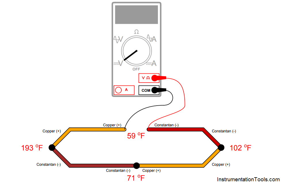
Suppose someone builds a dual-junction thermocouple circuit using type T thermocouple wire (copper and constantan metals), then measures voltage in the loop using a voltmeter:

Dual-junction thermocouple circuit

Calculate the voltage read by the voltmeter, using a type T thermocouple table to find millivolt potentials for each of the junctions.

Answer :

The voltmeter should read −3.908 millivolts. Counting all the junction voltages (with polarities shown in reference to whether they match or oppose the meter’s test lead polarity):

  • 193 oF junction = −3.789 mV
  • 71 oF junction = +0.857 mV
  • 102 oF junction = −1.565 mV
  • 59 oF junction = +0.589 mV
  • Loop total voltage = −3.908 mV

Hint: any junction pushing conventional flow in a counter-clockwise direction is regarded here as a “positive” figure. Any junction pushing in a clockwise direction is regarded as a “negative” figure.

The last junction (at 59 oF) may be treated as a single copper-constantan junction because the metal type of the meter’s test leads acts as an intermediate metal.

The fact that both the copper-testlead and constantantestlead junctions are at the same temperature allows us to disregard the test lead metal altogether and treat it as a single copper-constantan junction at 59 oF.

Don't Miss Our Updates
Be the first to get exclusive content straight to your email.
We promise not to spam you. You can unsubscribe at any time.
Invalid email address
You've successfully subscribed !

Continue Reading

Vertical Tube Liquid Level Equilibrium
Indentify Faults in Simple Lamp Circuit including Failed Wires
Programmable Logic Controller (PLC) Questions and Answers – 10
Practical Process Control System Questions & Answers – 9
Flow Transmitter Readings mismatch with DCS
Calculate Incident Power in Radar Level Measurement
Share This Article
Facebook Whatsapp Whatsapp LinkedIn Copy Link
Share
Leave a Comment

Leave a Reply Cancel reply

Your email address will not be published. Required fields are marked *

Stay Connected

128.3kFollowersLike
69.1kFollowersFollow
210kSubscribersSubscribe
38kFollowersFollow

Categories

Explore More

Float-type Level Switch for Sensing Low Oil Level
Sketch a Ladder Diagram for PLC to Energize the Lamp
Calculate Process Temperature using a Thermocouple
Determine the Pressure at Each Port of DP Transmitter
How to Draw a Schematic Diagram ?
Programmable Logic Controller (PLC) Questions and Answers – 5
Draw a ladder logic circuit for the electric motor of an air compressor ?
Identify the Problem in the PLC Program

Keep Learning

level control system

Practical Process Control System Questions & Answers – 11

Displacer Type Density Transmitter

Displacer Type Density Transmitter Question

PLC Motor Control Circuit

Motor Trip Logic using PLC Programming

Electronic Force Balance Pressure Transmitter

Electronic Force Balance Pressure Transmitter

Purge Type Level Transmitter

Purge Type Level Transmitter Questions

Identify which lamp in the following ladder-logic diagram

Identify High Flow Alarm and Low Flow Alarm?

Allen-Bradley MicroLogix 1000 controller

PLC Switch Actuation Status

Instrument Switch Status

Define Normal Status of a Process Switch ?

Learn More

Move function block

Move Instruction in Tia Portal

Thermostatic valves Principle

Thermostatic Valves Working Principle

Transformers Questions & Answers Part-4

Transformers Questions & Answers Part-4

Distribution transformer

Different Types of Transformers

Process Alarms Types

Process Switches and Alarms

WinCC data logging

How to Export Data from WinCC Runtime Advanced into Excel using VB Script

Differential Pressure Measurement across Baghouse

Differential Pressure Measurement across Baghouse

Snubber Circuits

Thyristor Protection Circuits (SCR) – Types, Principle, Explanation

Menu

  • About
  • Privacy Policy
  • Copyright

Quick Links

  • Learn PLC
  • Helping Hand
  • Part Time Job

YouTube Subscribe

Follow US
All rights reserved. Reproduction in whole or in part without written permission is prohibited.
Welcome Back!

Sign in to your account

Username or Email Address
Password

Lost your password?