The Analog Input (AI) function block processes field device measurements and makes them available to other function blocks. The output value from the AI block is in engineering units and contains a status indicating the quality of the measurement. The measuring device may have several measurements or derived values available in different channels. Use the channel number to define the variable that the AI block processes.
The AI block supports alarming, signal scaling, signal filtering, signal status calculation, mode control, and simulation. In Automatic mode, the block’s output parameter (OUT) reflects the process variable (PV) value and status. In Manual mode, OUT may be set manually. The Manual mode is reflected on the output status. A discrete output (OUT_D) is provided to indicate whether a selected alarm condition is active. Alarm detection is based on the OUT value and user specified alarm limits.
Simulation
To support testing, you can either change the mode of the block to manual and adjust the output value, or you can enable simulation through the configuration tool and manually enter a value for the measurement value and its status. In both cases, you must first set the ENABLE jumper on the field device. With simulation enabled, the actual measurement value has no impact on the OUT value or the status.
Analog Input Function Block Animation
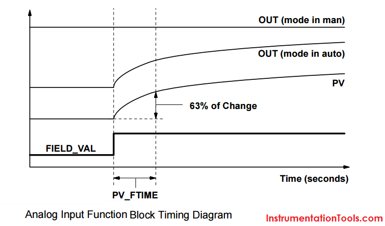
AI Function Block Timing Diagram:
The FIELD_VAL is the Process Variable and showing a step change in signal in the below figure. Consider a Flow transmitter with a step change from 10 to 50 m3/hr. When the Analog Input Block in Manual mode then the forced/last value is the output and the change in input signal i.e. Field_Val have no effect on the output. When the AI block in Auto the output responds to the change in input signal i.e. Field_val from 10 to 50 m3/hr and the output takes some time to respond the signal and it in-turn depends on PV_FTime (filtering time or damping).
Filtering
The filtering feature changes the response time of the device to smooth variations in output readings caused by rapid changes in input. You can adjust the filter time constant (in seconds) using the PV_FTIME parameter. Set the filter time constant to zero to disable the filter feature.
Signal Conversion (Formulas)
You can set the signal conversion type with the Linearization Type (L_TYPE) parameter. You can view the converted signal (in percent of XD_SCALE) through the FIELD_VAL parameter.

You can choose from direct, indirect, or indirect square root signal conversion with the L_TYPE parameter.
Direct
Direct signal conversion allows the signal to pass through the accessed channel input value (or the simulated value when simulation is enabled).
PV = Channel Value
Indirect
Indirect signal conversion converts the signal linearly to the accessed channel input value (or the simulated value when simulation is enabled) from its specified range (XD_SCALE) to the range and units of the PV and OUT parameters (OUT_SCALE).

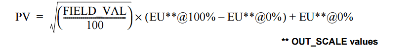
Indirect Square Root
Indirect Square Root signal conversion takes the square root of the value computed with the indirect signal conversion and scales it to the range and units of the PV and OUT parameters.
When the converted input value is below the limit specified by the LOW_CUT parameter, and the Low Cutoff I/O option (IO_OPTS) is enabled (True), a value of zero is used for the converted value (PV). This option is useful to eliminate false readings when the differential pressure measurement is close to zero, and it may also be useful with zero-based measurement devices such as flowmeters.
NOTE: Low Cutoff is the only I/O option supported by the AI block. You can set the I/O option in Manual or Out of Service mode only.
Modes
The AI Function Block supports three modes of operation as defined by the MODE_BLK parameter:
• Manual (Man) The block output (OUT) may be set manually.
• Automatic (Auto) reflects the analog input measurement or the simulated value when simulation is enabled.
• Out of Service (O/S) The block is not processed. FIELD_VAL and PV are not updated and the OUT status is set to Bad: Out of Service. The BLOCK_ERR parameter shows Out of Service. In this mode, you can make changes to all configured parameters. The target mode of a block may be restricted to one or more of the supported modes.
Alarm Detection
A block alarm will be generated whenever the BLOCK_ERR has an error bit set. The types of block error for the AI block are defined above.
Process Alarm detection is based on the OUT value. You can configure the alarm limits of the following standard alarms:
• High (HI_LIM)
• High high (HI_HI_LIM)
• Low (LO_LIM)
• Low low (LO_LO_LIM)
Status Handling
Normally, the status of the PV reflects the status of the measurement value, the operating condition of the I/O card, and any active alarm condition. In Auto mode, OUT reflects the value and status quality of the PV. In Man mode, the OUT status constant limit is set to indicate that the value is a constant and the OUT status is Good.
The Uncertain – EU range violation status is always set, and the PV status is set high- or low-limited if the sensor limits for conversion are exceeded. In the STATUS_OPTS parameter, you can select from the following options to control the status handling:
BAD if Limited – sets the OUT status quality to Bad when the value is higher or lower than the sensor limits.
Uncertain if Limited – sets the OUT status quality to Uncertain when the value is higher or lower than the sensor limits.
Uncertain if in Manual mode – The status of the Output is set to Uncertain when the mode is set to Manual
Advanced Features
The AI function block provided with Fisher-Rosemount fieldbus devices provides added capability through the addition of the following parameters:
ALARM_TYPE – Allows one or more of the process alarm conditions detected by the AI function block to be used in setting its
OUT_D parameter. OUT_D – Discrete output of the AI function block based on the detection of process alarm condition(s). This parameter may be linked to other function blocks that require a discrete input based on the detected alarm condition.
VAR_SCAN – Time period in seconds over which the variability index (VAR_INDEX) is computed.
VAR_INDEX – Process variability index measured as the integral of average absolute error between PV and its mean value over the previous evaluation period. This index is calculated as a percent of OUT span and is updated at the end of the time period defined by VAR_SCAN.


Do you have any video of that? I’d like to find out more details.
Sorry, No videos created. Thank you.