Inst ToolsInst ToolsInst Tools
  • Courses
  • Automation
    • PLC
    • Control System
    • Safety System
    • Communication
    • Fire & Gas System
  • Instrumentation
    • Design
    • Pressure
    • Temperature
    • Flow
    • Level
    • Vibration
    • Analyzer
    • Control Valve
    • Switch
    • Calibration
    • Erection & Commissioning
  • Interview
    • Instrumentation
    • Electrical
    • Electronics
    • Practical
  • Q&A
    • Instrumentation
    • Control System
    • Electrical
    • Electronics
    • Analog Electronics
    • Digital Electronics
    • Power Electronics
    • Microprocessor
  • Request
Search
  • Books
  • Software
  • Projects
  • Process
  • Tools
  • Basics
  • Formula
  • Power Plant
  • Root Cause Analysis
  • Electrical Basics
  • Animation
  • Standards
  • 4-20 mA Course
  • Siemens PLC Course
Reading: Fiber Optic Cable – Method of Joining and Fusion Splicing
Share
Font ResizerAa
Inst ToolsInst Tools
Font ResizerAa
  • Courses
  • Design
  • PLC
  • Interview
  • Control System
Search
  • Courses
  • Automation
    • PLC
    • Control System
    • Safety System
    • Communication
    • Fire & Gas System
  • Instrumentation
    • Design
    • Pressure
    • Temperature
    • Flow
    • Level
    • Vibration
    • Analyzer
    • Control Valve
    • Switch
    • Calibration
    • Erection & Commissioning
  • Interview
    • Instrumentation
    • Electrical
    • Electronics
    • Practical
  • Q&A
    • Instrumentation
    • Control System
    • Electrical
    • Electronics
    • Analog Electronics
    • Digital Electronics
    • Power Electronics
    • Microprocessor
  • Request
Follow US
All rights reserved. Reproduction in whole or in part without written permission is prohibited.
Inst Tools > Blog > Control Systems > Fiber Optic Cable – Method of Joining and Fusion Splicing

Fiber Optic Cable – Method of Joining and Fusion Splicing

Learn about the fiber optic cable operating principle, types, connectors, method of joining and fusion splicing.

Last updated: August 27, 2020 11:33 am
Editorial Staff
Control Systems
2 Comments
Share
6 Min Read
SHARE

Fiber Optic Cable

Fiber optic cable transmit information as light pulses, rather than the electrical impulses used by traditional wire cables. They may be used to convey voice, video and data.

Contents
Fiber Optic CableOperating PrincipleTypesConnectorsJoining Fiber Optic CablesFusion Splicing

Fiber Optic Cable

The fiber optic cables have a glass core covered with cladding, coatings, and, typically, Kevlar membranes to add strength. Finally, a protective outer coating seals the cables from the elements.

The cables may be connected to communications equipment and patch panels, providing any necessary physical connection.

Operating Principle

It is the optical fibers in the fiber optic cables that carry the light, and allow information to be transmitted. These consists of a core and a cladding layer, selected for total internal reflection due to the difference in the refractive index between the two.

fiber optic principle

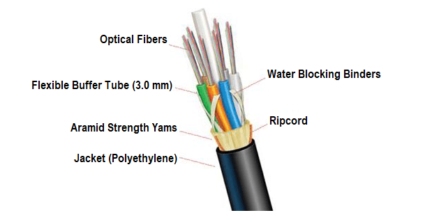
Individual coated fibers (or fibers formed into ribbons or bundles) then have a tough resin buffer layer and/or core tube(s) extruded around them to form the cable core. Protective sheathing is added for protection, depending on the application.

To prevent “cross-talk” between the fibers, sometimes they are encased in dark, light absorbing materials. This prevents the light from one fiber from leaking through to another. Several layers of protective sheathing, depending on the application, are added to form the cable.
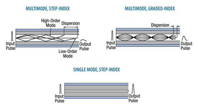
Types

The three types of fiber glass are shown here
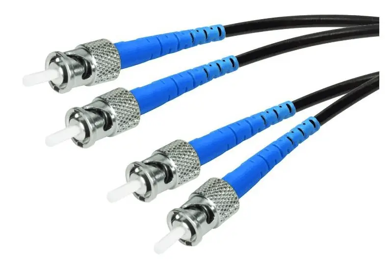
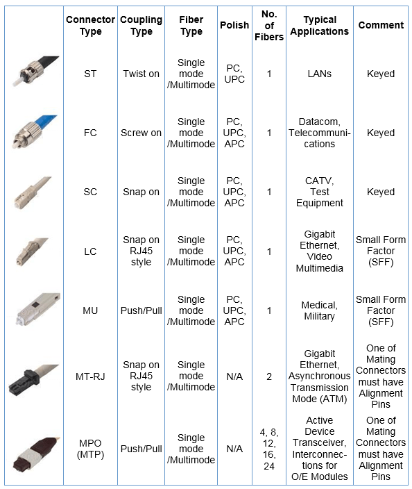
Types of fiber glass

Connectors

Commonly used connectors are shown in the table below.

Fiber optic Connectors

Joining Fiber Optic Cables

There are two methods of fiber optic splicing, fusion splicing & mechanical splicing. Splices are “permanent” connections between two fibers. Typically, the reason for choosing one method over the other is economics. Fusion splicing is lower per connection; however, the initial investment is much higher.

Mechanical splices are simply alignment devices, designed to hold the two fiber ends in a precisely aligned position thus enabling light to pass from one fiber into the other. (Typical loss: 0.3 dB). Mechanical splicing has a low initial investment, but costs more per splice.

When joining optical fibers, it is critical for the opposed cores to be properly aligned. The primary specification for connectors or splices is loss or the amount of light lost in the connection. Improper alignment where the optical fibers are not perfectly aligned will result in part of the light to be loss through the bad junction.

There are four main causes of optical loss mostly caused by:

1. Poor core alignment:

Poor alignment of joined optical fiber cores causes a connector/splice optical loss.

Poor alignment of joined optical fiber cores

2. Axial run-out:

A connector/splice optical loss occurs due to an axial run-out (improper cut angles) between the optical fibers to be joined.

It is necessary to avoid an increased angle at fiber cut end when using an optical fiber cleaver (cutting device) before fusion splicing, since such an angle can result in splicing of optical fibers with run-out.

angle at fiber cut end

3. Gap:

An end gap between optical fibers results in a connector/splice optical loss.

For example, if optical fiber end faces are not correctly butt-joined in mechanical splicing, a splice loss results due to the refraction of the light in the air gap between fibers.

An end gap between optical fibers results in 0.6 dB of return loss at the maximum due to the change in refractive index from the optical fiber to the air.

end gap between optical fibers

4. Reflection:

The end of the fiber must be properly polished and clean to minimize loss. A rough surface will scatter light and dirt can scatter and absorb light. Since the optical fiber is so small, typical airborne dirt can be a major source of loss.

Cleaning optical fiber ends is important for optical connectors.

In addition, the whole optical connector ends should be cleaned because loss can also occur due to dirt between optical connector ends.
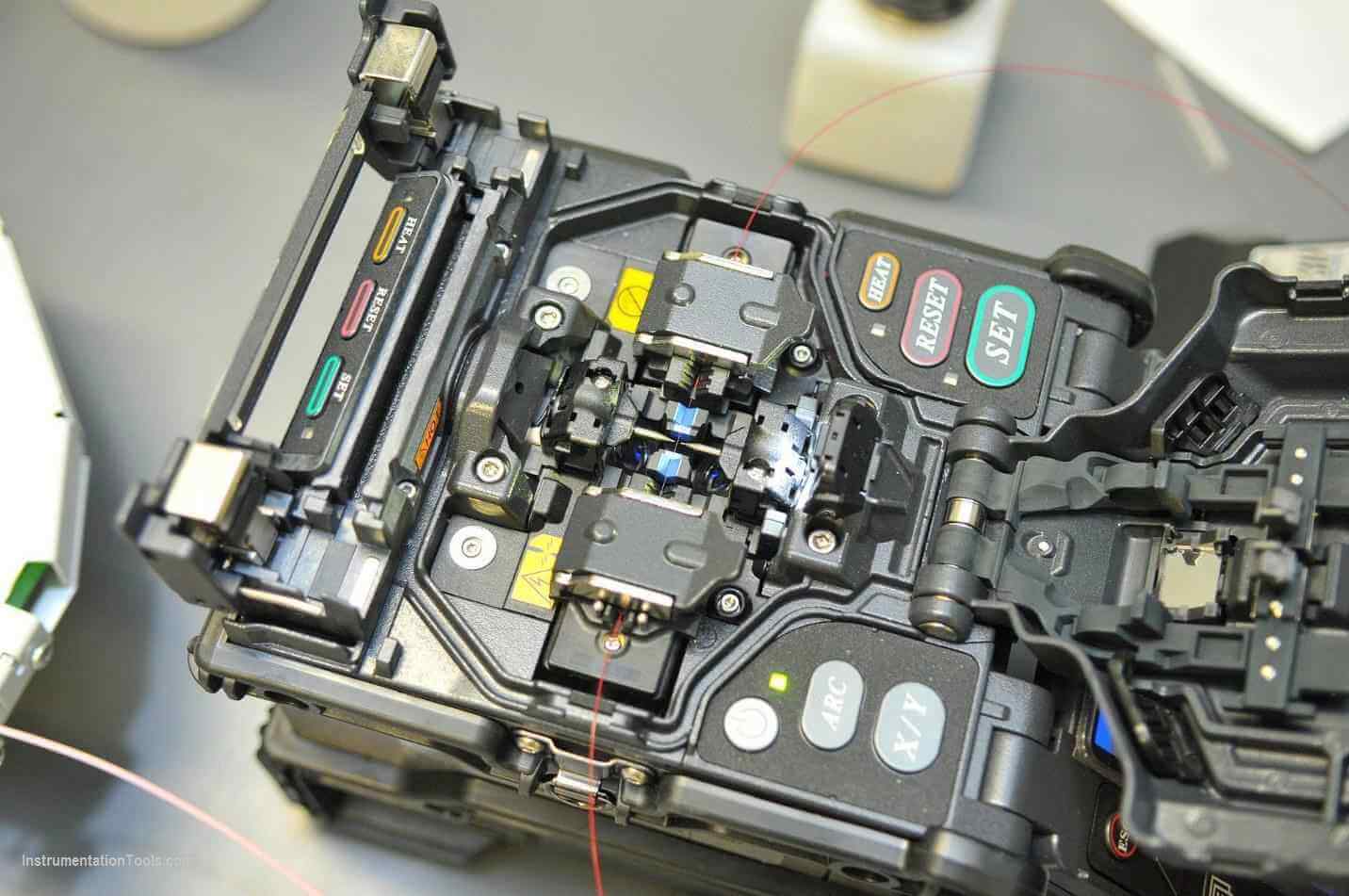
Fusion Splicing

Fusion splicing involves joining two optical fibers end-to-end using some source of heat.

The end result is fusing the two fibers together so that light passing through the fibers is not scattered or reflected back by the splice, and so that the splice and the region surrounding it are almost as strong as the virgin fiber itself.

Fiber Optic Cable Fusion Splicing

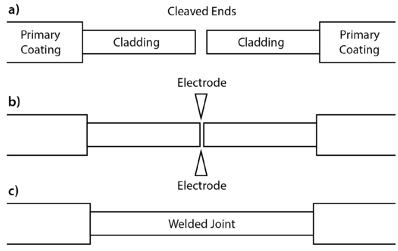
This produces a continuous connection between the fibers enabling very low loss light transmission. The source of heat is usually an electric arc, but can also be a laser, or a gas flame, or a tungsten filament through which current is passed.

Fusion splicing is the most widely used method of splicing as it provides for the lowest loss and least reflectance, as well as providing the strongest and most reliable joint between two fibers.

Fiber Optic Cable - Method of Joining and Fusion Splicing

Author: Mohammed Khaleel

Read Next:

  • Fiber Optic Cable Construction
  • Fiber Optic Connectors
  • Fiber Optic Communication
  • Industrial Automation Protocol
  • Optical Fiber bandwidth
Don't Miss Our Updates
Be the first to get exclusive content straight to your email.
We promise not to spam you. You can unsubscribe at any time.
Invalid email address
You've successfully subscribed !

Continue Reading

What are Static UPS and Rotary UPS?
Yokogawa DCS System Maintenance Procedures
Standard Colors in PLC Automation Systems
Anti-static Wrist Straps in Industrial Automation
How to Select the Right Type of Controller
Industry 4.0
Share This Article
Facebook Whatsapp Whatsapp LinkedIn Copy Link
Share
2 Comments
  • Mohd Shahid says:
    May 14, 2023 at 7:54 pm

    Very nice article on splicing

    Reply
  • Munmun Singh says:
    July 7, 2023 at 9:59 am

    Sir
    Thank you for sharing this information.

    Sir I request you to please reply my question.
    What is deference between HOP test and OTDR.

    Reply

Leave a Reply Cancel reply

Your email address will not be published. Required fields are marked *

Stay Connected

128.3kFollowersLike
69.1kFollowersFollow
210kSubscribersSubscribe
38kFollowersFollow

Categories

Explore More

Runaway Processes
Add On Instructions Programming – Analog Input Devices in Studio 5000
What is a Patch Panel? Types and Uses in Networking
Temperature Controller Problem
What is Instrument Hook Up Diagram ?
Top 5 Advantages of Human-Machine Interface (HMI)
DCS Program to Maintain Draft in Furnace
How to Analyze PID Controller Actions

Keep Learning

In this article, you will learn the configuration of PlantPAx library in factory talk studio of Rockwell Automation.

Configuration of PlantPAx Library in Factory Talk Studio

VFD Commissioning and Testing Procedure

VFD Commissioning and Testing Procedure (Variable Frequency Drive)

Siemens PLC Course for Beginners

Siemens PLC Course for Beginners: Problems and Solutions

Instrumentation Control Systems

What is Instrumentation Control System ?

annunciator-alarm-simulator

Alarm Simulator for Annunciator Logic

Impressed Current Galvanic System

Types of Cathodic Protection for Pipeline Protection

Electrical and Instrument Engineers Job Profile

Instrumentation and Electrical Teams Interactions (Detail Design Engineering)

List of 100 Questions Related to Distributed Control Systems (DCS)

List of 100 Distributed Control Systems Questions (DCS)

Learn More

Digital Electronics Multiple Choice Questions

Register-Transistor Logic (RTL) Objective Questions

TP Timer in CodeSys

Timers in Codesys – Timer ON, Timer OFF, Pulse Timer

Oil in Water Analyzer Principle

Oil in Water Analyzer Working Principle

Top Electrical Engineering Questions & Answers

Top Electrical Engineering Questions & Answers

What is a Dosing Pump? - Types, Advantages, Applications

What is a Dosing Pump? – Types, Advantages, Applications

Electrical Machines Objective Questions

Electrical Machines MCQ Series 7

P&ID

Over Pressure Protection Devices

Commissioning Differential Pressure Transmitter in Boiler Steam Drum

Commissioning a Differential Pressure Transmitter in a Pressurized Boiler Steam Drum

Menu

  • About
  • Privacy Policy
  • Copyright

Quick Links

  • Learn PLC
  • Helping Hand
  • Part Time Job

YouTube Subscribe

Follow US
All rights reserved. Reproduction in whole or in part without written permission is prohibited.
Welcome Back!

Sign in to your account

Username or Email Address
Password

Lost your password?