This article discusses the exercise with delay timers (TON and TOFF) in the Siemens TIA Portal programming. The TON timer is used to delay activating the output after the input becomes active (ON). When the specified time (preset time) is reached, the timer output will turn on (ON). Conversely, the TOFF Timer functions to delay output shutdown after the input becomes inactive (OFF). During the preset time, the output remains active, and after the time ends, the output will turn OFF.
Program Objective
Timer TON (Timer On Delay) Sequence of Operation:
- Start: When the Trigger button is Pressed, the system will Start.
- Lamp 1 Turns On: Lamp-1 will turn ON, indicating that the first TON timer has started counting.
- 6-Second Countdown: The first TON timer will count down for 6 seconds.
- Lamp 1 Turns Off, Lamp 2 Turns On: After 6 seconds, Lamp-1 will turn Off, and Lamp-2 will turn On, indicating the second TON timer has started counting.
- 5-Second Countdown: The second TON timer will count down for 5 seconds.
- Reset First Timer: After 5 seconds, the first TON timer will reset, and the cycle will repeat.
- Repeat: The process will continue as long as the Stop button is not Pressed.
Timer TOFF (Timer Off Delay) Sequence of Operation:
This sequence uses Positive Signal Edge and Negative Signal Edge contacts.
- Start: When the Trigger button is Pressed (momentarily), the system will Start.
- 7-Second Countdown: The first TOFF timer will count down for 7 seconds.
- Lamp 3 Turns On: While the first TOFF timer is counting down, Lamp-3 will be ON.
- Lamp 3 Turns Off: After 7 seconds, Lamp-3 will turn Off.
- 5-Second Countdown: The second TOFF timer will Start counting down for 5 seconds.
- Lamp 4 Turns On: While the second TOFF timer is counting down, Lamp-4 will be ON.
- Lamp 4 Turns Off: After 5 seconds, Lamp-4 will turn off, and the first TOFF timer will Start counting again.
- Repeat: The process will continue as long as the Stop button is not Pressed.
Siemens TIA Portal Timer Programming
Mapping Details
| S.No. | Comment | Input (I) | Output (Q) | Memory Bit | Timer |
|---|---|---|---|---|---|
| 1 | START | I0.0 | |||
| 2 | STOP | I0.1 | |||
| 3 | TRIGGER_TON | I0.2 | |||
| 4 | TRIGGER_TOFF | I0.3 | |||
| 5 | LAMP_1 | Q0.0 | |||
| 6 | LAMP_2 | Q0.1 | |||
| 7 | LAMP_3 | Q0.2 | |||
| 8 | LAMP_4 | Q0.3 | |||
| 9 | TON_1 | DB1 | |||
| 10 | TON_2 | DB2 | |||
| 11 | TOFF_1 | DB3 | |||
| 12 | TOFF_2 | DB4 | |||
| 13 | SYSTEM_ON | M0.0 | |||
| 14 | IR_TON | M0.1 | |||
| 15 | IR_TON1 | M0.2 | |||
| 16 | IR_TON2 | M0.3 | |||
| 17 | IR_TOFF1 | M0.4 | |||
| 18 | IR_TOFF2 | M0.5 | |||
| 19 | IR_TOFF1.1 | M0.6 | |||
| 20 | IR_TOFF2.1 | M0.7 | |||
| 21 | IR_TRIGGER_TOFF | M1.0 |
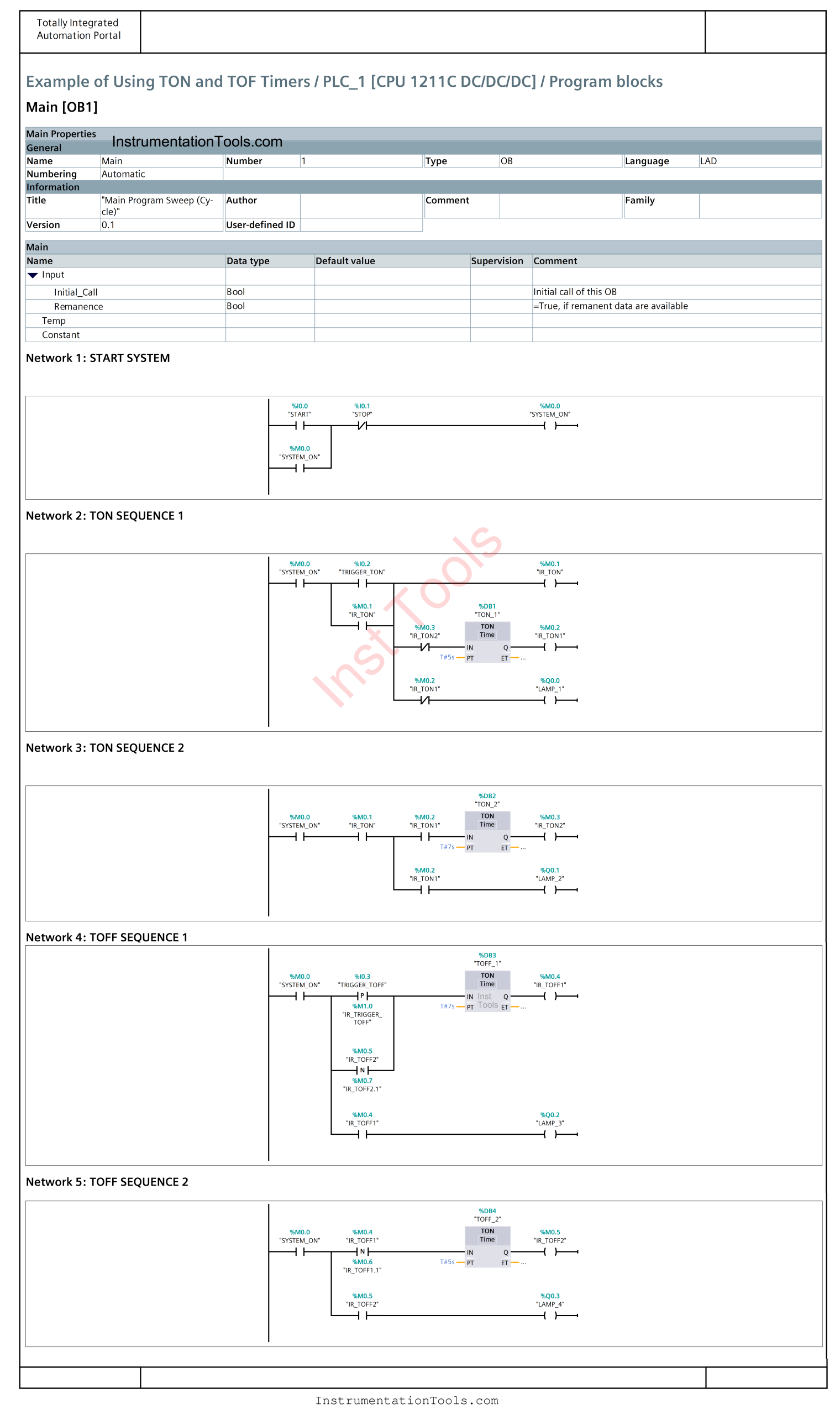
Exercise with Delay Timers
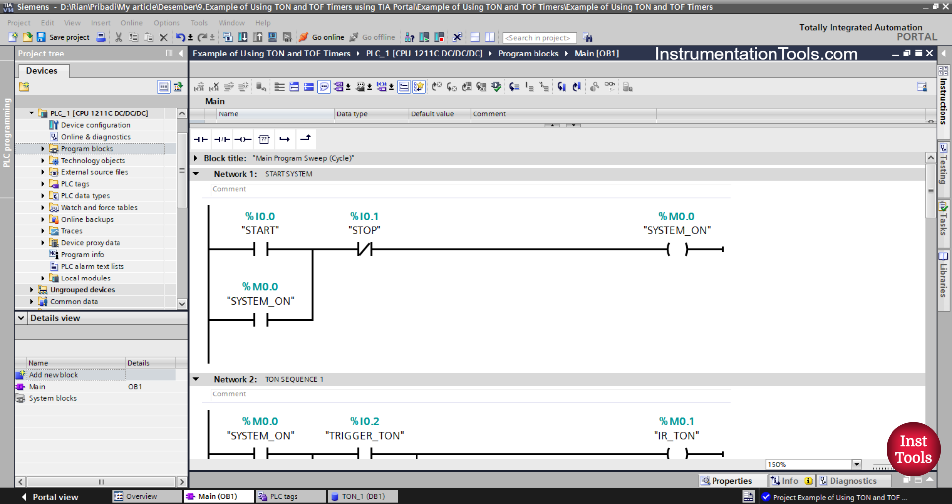
NETWORK 1 (START SYSTEM)
In this Network, when the START (I0.0) button is pressed, the memory bit SYSTEM_ON (M0.0) will be in the HIGH state. Even though the START (I0.0) button has been released, the memory bit SYSTEM_ON (M0.0) will remain in the HIGH state. Because it uses Latching.
The memory bit SYSTEM_ON (M0.0) will be in the LOW state if the STOP (I0.1) button is pressed.
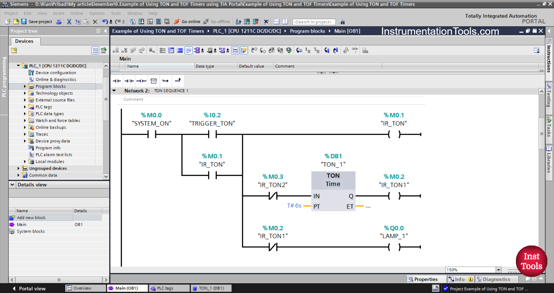
NETWORK 2 (TON SEQUENCE 1)
In this Network, the memory bit IR_TON (M0.1) will be in the HIGH state, and the output LAMP_1 (Q0.0) will be ON when the NO contact of the memory bit SYSTEM_ON (M0.0) is in the HIGH state and the TRIGGER_TON (I0. 2) button has been pressed. Timer TON_1 (DB1) Starts counting up to 6 seconds.
Because it uses Latching, even though the TRIGGER_TON (I0.2) button has been released, the memory bit IR_TON (M0.1) will remain in the HIGH state.
When Timer TON_1 (DB1) has finished counting, the output LAMP_1 (Q0.0) will be OFF and the memory bit IR_TON1 (M0.2) will be in the HIGH state.
Timer TON_1 (DB1) will be reset when the NC contact of the memory bit IR_TON2 (M0.3) is in the HIGH state.
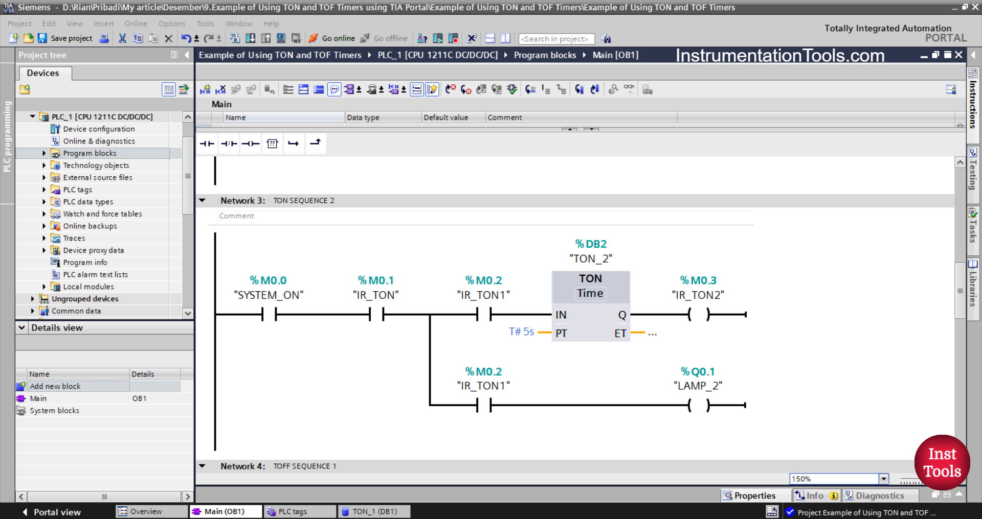
NETWORK 3 (TON SEQUENCE 2)
In this Network, the NO contact of the memory bit SYSTEM_ON (M0.0) and the memory bit IR_TON (M0.1) are in the HIGH state. Then the timer TON_1 (DB1) starts counting up to 5 seconds and the output LAMP_1 (Q0.0) becomes ON.
When Timer TON_1 (DB1) has finished counting, the memory bit IR_TON2 (M0.3) will be in the HIGH state.
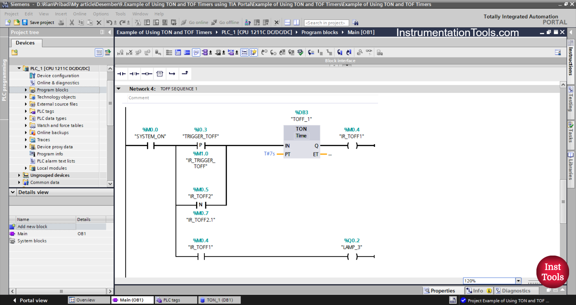
NETWORK 4 (TOFF SEQUENCE 1)
In this Network, Timer TOFF_1 (DB3) starts counting when the NO contact of the memory bit SYSTEM_ON (M0.0) in the HIGH state and the TRIGGER_TOFF (I0.3) button are pressed.
The TRIGGER_TOFF (I0.3) button will provide a momentary Trigger to Timer TOFF_1 (DB3) when conditions change from LOW to HIGH state. Because the TRIGGER_TOFF button (I0.3) uses a NO contact of the Positive Signal Edge type.
Next, Timer TOFF_1 (DB3) counts up to 7 seconds. The output LAMP_3 (Q0.2) will be ON, and the memory bit IR_TOFF1 (M0.4) will be in HIGH state for 7 seconds.
When the NO contact of memory bit IR_TOFF1 (M0.4) is in a HIGH state, it will provide a momentary trigger to Timer TOFF_1 (DB3) again.
Because the NO memory bit contact IR_TOFF1 (M0.4) uses the Negative Signal Edge type, the TOFF_1 Timer (DB3) will receive a momentary trigger when the state of the NO memory bit contact IR_TOFF1 (M0.4) changes from HIGH to LOW.
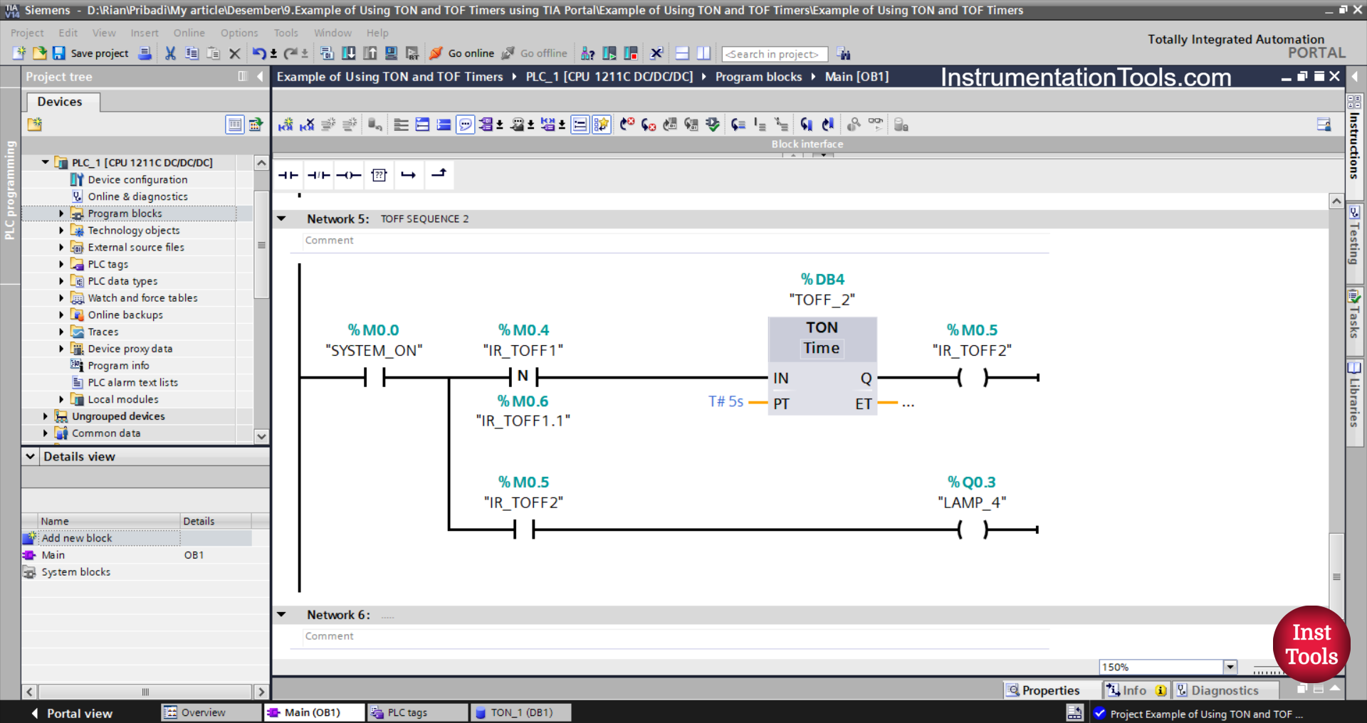
NETWORK 5 (TOFF SEQUENCE 2)
Next, the timer TOFF_2(DB4) will start counting when the NO contacts of the memory bit SYSTEM_ON(M0.0) and IR_TOFF1 (M0.4) are in the HIGH state.
Because the NO contact of the memory bit IR_TOFF 1(M0.4) uses a Negative Signal Edge type contact, then the Timer TOFF_2(DB4) will receive a momentary trigger when the condition changes from HIGH to LOW state of the NO contact memory bit IR_TOFF1 (M0.4).
TOFF_2 (DB4) will count up to 5 seconds, output LAMP_3 (Q0.2) will be ON, and memory bit IR_TOFF2(M0.5) will be in HIGH state for 5 seconds.
Read Next:
- PLC Logic Street Light Control Based on Light Intensity
- Escalator Speed Control based on Users with PLC
- Practical Example of TON and TOFF Timers in XG5000
- Siemens TIA Portal Example for Weight Classification
- Siemens TIA Portal Sequential Control Logic Example