Inst ToolsInst ToolsInst Tools
  • Courses
  • Videos
  • Q & A
    • Interview
      • Instrumentation
      • Electronics
      • Electrical
      • Practical Questions
    • MCQ
      • Instrumentation MCQ
      • Electrical MCQ
      • Electronics MCQ
      • Control Systems MCQ
      • Analog Electronics MCQ
      • Digital Electronics MCQ
      • Power Electronics MCQ
      • Microprocessor MCQ
      • Multiple Choice Questions
  • EE
    • Electronics
      • Electronics Q & A
      • Electronic Basics
      • Electronic Devices & Circuits
      • Electronics Animation
      • Digital Electronics
    • Electrical
      • Electrical Basics
      • Electrical Q & A
      • Power Electronics
      • Electrical Machines
      • Electrical Animation
      • Power Systems
      • Switchgear & Protection
      • Transmission & Distribution
  • Measure
    • Control Valves
    • Calibration
    • Temperature
    • Pressure
    • Flow
    • Level
    • Analyzers
    • Switches
    • Vibration
    • Solenoid Valve
  • Control
    • PLC Tutorials
    • Control Systems
    • Safety Instrumented System (SIS)
    • Communication
    • Fire & Gas System
  • More
    • Design
    • Tools
    • Animation
    • Basics
    • Formulas
    • Standards
    • TextBooks
    • Common
    • Software
    • Excel Tools
    • Erection & Commissioning
    • Process Fundamentals
    • Videos
    • Books
Search
All rights reserved. Reproduction in whole or in part without written permission is prohibited.
Font ResizerAa
Inst ToolsInst Tools
Font ResizerAa
  • Courses
  • PLC Tutorials
  • Control Systems
Search
  • Courses
  • Videos
  • Q & A
    • Interview
    • MCQ
  • EE
    • Electronics
    • Electrical
  • Measure
    • Control Valves
    • Calibration
    • Temperature
    • Pressure
    • Flow
    • Level
    • Analyzers
    • Switches
    • Vibration
    • Solenoid Valve
  • Control
    • PLC Tutorials
    • Control Systems
    • Safety Instrumented System (SIS)
    • Communication
    • Fire & Gas System
  • More
    • Design
    • Tools
    • Animation
    • Basics
    • Formulas
    • Standards
    • TextBooks
    • Common
    • Software
    • Excel Tools
    • Erection & Commissioning
    • Process Fundamentals
    • Videos
    • Books
Follow US
All rights reserved. Reproduction in whole or in part without written permission is prohibited.
Inst Tools > Blog > Control Systems > Waste Water Control System

Waste Water Control System

Last updated: July 29, 2019 3:54 am
Editorial Staff
Control Systems
No Comments
Share
5 Min Read
SHARE

The final step in treating waste water before releasing it into the natural environment is to kill any harmful microorganisms (e.g. viruses, bacteria) in it. This is called disinfection, and chlorine gas is a very effective disinfecting agent.

However, just as it is not good to mix too little chlorine in the outgoing water (effluent) because we might not disinfect the water thoroughly enough, there is also danger of injecting too much chlorine in the effluent because then we might begin poisoning animals and beneficial microorganisms in the natural environment.

To ensure the right amount of chlorine injection, we must use a dissolved chlorine analyzer to measure the chlorine concentration in the effluent, and use a controller to automatically adjust the chlorine control valve to inject the right amount of chlorine at all times.

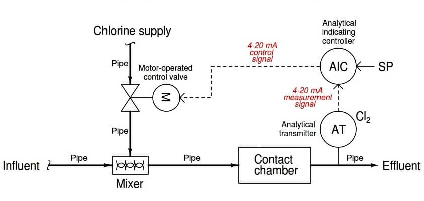
The following P&ID (Piping and Instrument Diagram) shows how such a control system might look:

Waste Water Control System

Waste Water Control System

Chlorine gas coming through the control valve mixes with the incoming water (influent), then has time to disinfect in the contact chamber before exiting out to the environment.

The transmitter is labeled “AT” (Analytical Transmitter) because its function is to analyze the concentration of chlorine dissolved in the water and transmit this information to the control system. The “Cl ” (chemical notation for a chlorine molecule) written near the transmitter bubble declares this to be a chlorine analyzer.

The dashed line coming out of the transmitter tells us the signal is electric in nature, not pneumatic as was the case in the previous (boiler control system) example.

The most common and likely standard for electronic signaling in industry is 4 to 20 milliamps DC, which represents chlorine concentration in much the same way as the 3 to 15 PSI pneumatic signal standard represented steam drum water level in the boiler:

Water Treatment Control System table

The controller is labeled “AIC” because it is an Analytical Indicating Controller. Controllers are always designated by the process variable they are charged with controlling, in this case the chlorine analysis of the effluent.

“Indicating” means there is some form of display that a human operator or technician can read showing the chlorine concentration. “SP” refers to the setpoint value entered by the operator, which the controller tries to maintain by adjusting the position of the chlorine injection valve.

A dashed line going from the controller to the valve indicates another electronic signal: a 4 to 20 mA direct current signal again. Just as with the 3 to 15 PSI pneumatic signal standard in the pneumatic boiler control system, the amount of electric current in this signal path directly relates to a certain valve position:

Water Treatment Control System Signals

Note: it is possible, and in some cases even preferable, to have either a transmitter or a control valve that responds in reverse fashion to an instrument signal such as 3 to 15 PSI or 4 to 20 milliamps.

For example, this valve could have been set up to be wide open at 4 mA and fully shut at 20 mA. The main point to recognize here is that both the process variable sensed by the transmitter and the position of the control valve are proportionately represented by analog signals.

A common misconception for people first learning about analog instrumentation signals is to assume the transmitter’s signal (“Process Variable”) must be identical in value to the control valve’s signal (“Manipulated Variable” or “Output”), but this is not true.

The letter “M” inside the control valve bubble tells us this is a motor-actuated valve. Instead of using compressed air pushing against a spring-loaded diaphragm as was the case in the boiler control system, this valve is actuated by an electric motor turning a gear-reduction mechanism.

The gear reduction mechanism allows slow motion of the control valve stem even though the motor spins at a fast rate. A special electronic control circuit inside the valve actuator modulates electric power to the electric motor in order to ensure the valve position accurately matches the signal sent by the controller.

In effect, this is another control system in itself, controlling valve position according to a “setpoint” signal sent by another device (in this case, the AIT controller which is telling the valve what position to go to).
Don't Miss Our Updates
Be the first to get exclusive content straight to your email.
We promise not to spam you. You can unsubscribe at any time.
Invalid email address
You've successfully subscribed !

Continue Reading

Basics of Wellhead Control Panel (WHCP)
Project Planning and Implementation of PLC or DCS Control System
Fault in the Temperature Loop
Industrial Automation Pre-Engineering Design Documents – Project & Process
What is Ratio Control ?
Distributed Control System Objective Questions
Share This Article
Facebook Copy Link Print
Share
Leave a Comment

Leave a Reply Cancel reply

Your email address will not be published. Required fields are marked *

Stay Connected

128.3kFollowersLike
69.1kFollowersFollow
208kSubscribersSubscribe
38kFollowersFollow

Categories

Explore More

What is Process Control?
Feedback Control Principle
Process Control Automation PLC Quiz
Design Process Graphics in Factory Talk View Studio with an Analog Input
Interactions With Process Control Systems Philosophy
Two Element Drum Level Control System
Sink or Source? Normally Open or Normally Closed?
Ziegler-Nichols Open Loop Tuning Procedure
Readings Mismatch between Field & Control Room ? Why
Control System Architecture

Keep Learning

Identify Instruments in Piping and instrumentation Diagram

Identify Instruments in Piping and instrumentation Diagram

What is Static Grounding

What is Static Grounding?

Supervisory Control

Supervisory Control

Digital output block add-on for Variable speed drive

Steps to Import PlantPAx Add-On Instructions in Studio 5000

ICS Control System

ICS Control System Security

Two out of Three Logic Analogy

How-to do Security of SCADA Systems

How-to do Security of SCADA Systems?

Alarm Management Practices

Control Room Alarm Management Practices

Discover More

What is WHCP?

Network Theorems Objective Questions and Answers

Network Theorems Objective Questions and Answers

Steam Generator Parts

Parts and functions of Steam Turbine

Orifice Taps

Orifice Plate Tapping – Orifice Plate Taps

PLC Example on Switch Program with Timers

PLC Example on Switch Program with Timers

FF JB Termination

Foundation Fieldbus Installation and Best Practices

Structured Text Automatic Gate Logic

Structured Text PLC Programming for Automatic Gate Control

Ion Analyzers Questions and Answers

Ion Selective Electrodes Questions and Answers

Follow US
All rights reserved. Reproduction in whole or in part without written permission is prohibited.
Welcome Back!

Sign in to your account

Username or Email Address
Password

Lost your password?