Inst ToolsInst ToolsInst Tools
  • Courses
  • Automation
    • PLC
    • Control System
    • Safety System
    • Communication
    • Fire & Gas System
  • Instrumentation
    • Design
    • Pressure
    • Temperature
    • Flow
    • Level
    • Vibration
    • Analyzer
    • Control Valve
    • Switch
    • Calibration
    • Erection & Commissioning
  • Interview
    • Instrumentation
    • Electrical
    • Electronics
    • Practical
  • Q&A
    • Instrumentation
    • Control System
    • Electrical
    • Electronics
    • Analog Electronics
    • Digital Electronics
    • Power Electronics
    • Microprocessor
  • Request
Search
  • Books
  • Software
  • Projects
  • Process
  • Tools
  • Basics
  • Formula
  • Power Plant
  • Root Cause Analysis
  • Electrical Basics
  • Animation
  • Standards
  • 4-20 mA Course
  • Siemens PLC Course
Reading: Energize to Safe Loop philosophy
Share
Notification Show More
Font ResizerAa
Inst ToolsInst Tools
Font ResizerAa
  • Courses
  • Design
  • PLC
  • Interview
  • Control System
Search
  • Courses
  • Automation
    • PLC
    • Control System
    • Safety System
    • Communication
    • Fire & Gas System
  • Instrumentation
    • Design
    • Pressure
    • Temperature
    • Flow
    • Level
    • Vibration
    • Analyzer
    • Control Valve
    • Switch
    • Calibration
    • Erection & Commissioning
  • Interview
    • Instrumentation
    • Electrical
    • Electronics
    • Practical
  • Q&A
    • Instrumentation
    • Control System
    • Electrical
    • Electronics
    • Analog Electronics
    • Digital Electronics
    • Power Electronics
    • Microprocessor
  • Request
Follow US
All rights reserved. Reproduction in whole or in part without written permission is prohibited.
Inst Tools > Blog > Control Systems > Energize to Safe Loop philosophy

Energize to Safe Loop philosophy

Last updated: March 22, 2019 10:26 am
Editorial Staff
Control Systems Safety Instrumented System (SIS)
4 Comments
Share
3 Min Read
SHARE

Safety Instrument loop in a plant operate in two modes:

  1. Energized to safe
  2. De-energized to safe

Energized to safe mode works as contrary to that of De-energized to safe loop.

In Energized to safe loop, no electrical current flows through the instrument loop during plant normal condition. Loop will be energized during plant upset/trip/shutdown.

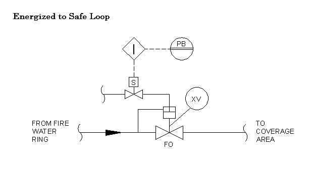
Energize to Safe Loop

Energize to Safe Loop philosophy

For illustration, see above picture of a simple unit consisting push button (PB) and solenoid valve controlling a deluge valve (XV). During plant normal condition (no fire) the push button contact is at open position so that no current flows within the loop.

Similarly, the solenoid valve of deluge valve is not being energized by electrical power. This condition drives the deluge valve to close position, prevents the fire water from ring main passing through the deluge valve.

If there is a fire in deluge coverage area, someone would activate the push button. Once activated, the switch within push button changes state to close position and enables electrical current flows within the loop.

This current will signal the control system and execute the predetermined action i.e. to open deluge valve by energizing the solenoid valve loop.

Therefore, once the solenoid valve energized, it will make the deluge valve to open, allowing water flows through to extinguish fire.

This mode is also commonly applied for ESD push button for shutting down a plant.

The purpose of having energized to safe system in such system is to avoid mis-operation of final element (activation of deluge valve on above example) due to instrument failure or unintended instrument cable disconnection.

Imagine if this system applies de-energized to safe mode instead. Even only one failure on solenoid valve cable or system side fault e.g. I/O card, will cause the deluge to open automatically.

Not only will this cause the equipment including surrounding instruments to wet, but this will also be dangerous as the equipment within the area is still not electrically isolated.Worse would happen in ESD push button, as it will cause a plant shutdown that results in production loss.

Additional Fact: Deluge valve is also activated by confirmed fire signal generated by flame detector, smoke detector or heat detector.
Articles You May Like :

2-way Solenoid Valve

Deluge System Protection

Fire Water Spray Systems

Types of Control Systems

Series Open Circuit Faults

Don't Miss Our Updates
Be the first to get exclusive content straight to your email.
We promise not to spam you. You can unsubscribe at any time.
Invalid email address
You've successfully subscribed !

Continue Reading

High Reliability of Safety Instrumented Systems
14 Basic Control Systems Questions for Interview Preparation
Identify Faults in PID Control Loop
Basics for CAN Bus Protocol – Controller Area Network
Instrumentation Cyber Security Glossary
Design View of Supplying Process Control and Safety Systems
Share This Article
Facebook Whatsapp Whatsapp LinkedIn Copy Link
Share
4 Comments
  • Sathit says:
    September 20, 2016 at 2:11 am

    Interesting, never seen this , just thinking about fail-safe mode which is energizes instrument in normal operation.

    Reply
  • moljengo says:
    September 20, 2016 at 8:20 am

    Bro,
    nice work you are doing out here educating the rest of the world by sharing your knowledge thanks a lot .
    please do include that nice print button again so that we can read and re read your article offline.
    thanks once again as i hope you will honor my request.

    Reply
    • S Bharadwaj Reddy says:
      September 20, 2016 at 8:38 am

      Hi, Thanks for the support. Recently website updated. I am facing a problem with print/pdf option. Hope the problem will be solved soon.

      Reply
  • MK says:
    October 17, 2017 at 4:53 pm

    GREAT THANX

    Reply

Leave a Reply Cancel reply

Your email address will not be published. Required fields are marked *

Stay Connected

128.3kFollowersLike
69.1kFollowersFollow
210kSubscribersSubscribe
38kFollowersFollow

Categories

Explore More

Applying Probability Laws to a Safety Instrumented System
Emergency Shutdown Valve : Advantages
Background of Modbus – ASCII and RTU Data Frames
On/off Control Theory
PID Controller Loop Tuning Questions and Answers – Part 2
Motor Control using Modbus Communication and Hardwired Signals
What is Alarm Prioritization? – Types of Alarms
De-energize to Safe Loop philosophy

Keep Learning

Electromagnetic Noise Interference

What is Electromagnetic Noise Interference?

Anti-static Wrist Straps

Anti-static Wrist Straps in Industrial Automation

feedforward control theory

Proportioning Feedforward action

MODBUS ASCII Communication Protocol Explained

MODBUS ASCII Communication Protocol Explained

DCS Vs PLC

DCS versus PLC Architecture

SIS Verification & Validation - Safety Instrumented System

SIS Verification & Validation – Safety Instrumented System

Switches, Repeaters, Bridges, Routers, Firewalls

Switches, Repeaters, Bridges, Routers, Firewalls

LIC and FIC Controllers

What LIC and FIC Controllers will do?

Learn More

Instrumentation documents

Instrumentation documents

valve trim characteristics

Control Valve Trim Characteristics

LIFO Instruction in Allen Bradley PLC Programming

LIFO Instruction in PLC

LED Indications on PLC

Getting to Know the LED Indications on GE Make PLC

Closed-tank-DP-Level-Transmitter-with-wet-leg-elevation-zero-direct-mount-Calibration

Closed tank DP Level Transmitter with wet leg elevation zero direct mount Calibration

Online PLC Ladder Logic

Mis-conceptions of PLC Ladder Logic

Cable screen shall not be grounded

Cable Screen shall not be Grounded at Field Device ?

Fire Hydrant System

Basics of Fire Fighting Hydrant Systems

Menu

  • About
  • Privacy Policy
  • Copyright

Quick Links

  • Learn PLC
  • Helping Hand
  • Part Time Job

YouTube Subscribe

Follow US
All rights reserved. Reproduction in whole or in part without written permission is prohibited.
Welcome Back!

Sign in to your account

Username or Email Address
Password

Lost your password?