A simple form of electronic pressure sensor could be made with a bourdon tube and a Linear Variable Differential Transformer, or LVDT.
Pressure Sensor with Bourdon Tube and LVDT
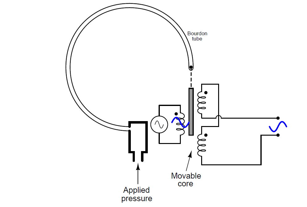
Explain how this instrument works, what type of electrical output signal it generates (e.g. current, voltage, resistance, etc.), and what polarity (if any) that output signal has.
Answer:
Note very carefully how the two secondary coils are connected in series-opposing (as denoted by the phase dots)! This detail is essential in figuring out how the LVDT works.
The output is an AC voltage, the magnitude of which is proportional to core position, which in turn is proportional to applied pressure. For what it’s worth, the phase of the output voltage will be inverted with respect to the excitation voltage as the bourdon tube draws the core up:
LVDTs have several advantages over potentiometers:
- No friction
- No wear
- No potential to generate a spark in normal operating conditions
Their major disadvantage is requiring an AC excitation voltage. The frequency of this excitation voltage is important as well: it must be much larger than the highest frequency of pressure changes you wish to measure (as per the Nyquist sampling theorem).
Pressure Sensor with Bourdon Tube and Capacitor
A simple form of electronic pressure transmitter could be made with a bourdon tube and a differential capacitor:
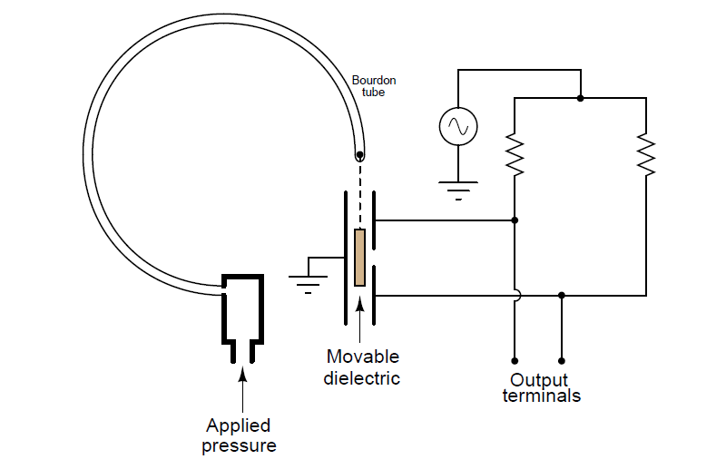
Explain how this instrument works, what type of electrical output signal it generates (e.g. current, voltage, resistance, etc.), and what polarity (if any) that output signal has.
Answer:
Although it may not look like it at first, the two resistors form a bridge circuit with the differential capacitor.
Share your answers with us through below comments section.
Read Next:
- Types of Bourdon Tube
- Strain Gauge Principle
- Solenoid Actuated Valves
- Types of Thermometers
- Electrical Signal Types
Credits: Tony R. Kuphaldt