Inst ToolsInst ToolsInst Tools
  • Courses
  • Videos
  • Q & A
    • Interview
      • Instrumentation
      • Electronics
      • Electrical
      • Practical Questions
    • MCQ
      • Instrumentation MCQ
      • Electrical MCQ
      • Electronics MCQ
      • Control Systems MCQ
      • Analog Electronics MCQ
      • Digital Electronics MCQ
      • Power Electronics MCQ
      • Microprocessor MCQ
      • Multiple Choice Questions
  • EE
    • Electronics
      • Electronics Q & A
      • Electronic Basics
      • Electronic Devices & Circuits
      • Electronics Animation
      • Digital Electronics
    • Electrical
      • Electrical Basics
      • Electrical Q & A
      • Power Electronics
      • Electrical Machines
      • Electrical Animation
      • Power Systems
      • Switchgear & Protection
      • Transmission & Distribution
  • Measure
    • Control Valves
    • Calibration
    • Temperature
    • Pressure
    • Flow
    • Level
    • Analyzers
    • Switches
    • Vibration
    • Solenoid Valve
  • Control
    • PLC Tutorials
    • Control Systems
    • Safety Instrumented System (SIS)
    • Communication
    • Fire & Gas System
  • More
    • Design
    • Tools
    • Animation
    • Basics
    • Formulas
    • Standards
    • TextBooks
    • Common
    • Software
    • Excel Tools
    • Erection & Commissioning
    • Process Fundamentals
    • Videos
    • Books
Search
All rights reserved. Reproduction in whole or in part without written permission is prohibited.
Reading: Effect of Differential Pressure on Control Valve Lift
Share
Notification Show More
Font ResizerAa
Inst ToolsInst Tools
Font ResizerAa
  • Courses
  • PLC Tutorials
  • Control Systems
Search
  • Courses
  • Videos
  • Q & A
    • Interview
    • MCQ
  • EE
    • Electronics
    • Electrical
  • Measure
    • Control Valves
    • Calibration
    • Temperature
    • Pressure
    • Flow
    • Level
    • Analyzers
    • Switches
    • Vibration
    • Solenoid Valve
  • Control
    • PLC Tutorials
    • Control Systems
    • Safety Instrumented System (SIS)
    • Communication
    • Fire & Gas System
  • More
    • Design
    • Tools
    • Animation
    • Basics
    • Formulas
    • Standards
    • TextBooks
    • Common
    • Software
    • Excel Tools
    • Erection & Commissioning
    • Process Fundamentals
    • Videos
    • Books
Follow US
All rights reserved. Reproduction in whole or in part without written permission is prohibited.
Inst Tools > Blog > Control Valves > Effect of Differential Pressure on Control Valve Lift

Effect of Differential Pressure on Control Valve Lift

Last updated: September 30, 2019 5:14 pm
Editorial Staff
Control Valves
1 Comment
Share
6 Min Read
SHARE

The air fed into the diaphragm chamber is the control signal from the pneumatic controller. The most widely used signal air pressure is 0.2 bar to 1 bar.

Contents
Effect of Differential Pressure on Control ValveArticles You May Like :Control Valve Erosion ProblemsThermostatic valves PrinciplePressure to Current ConverterMixing or Diverting ValveReverse Acting Valves

Consider a reverse acting actuator (spring-to-extend) with standard 0.2 to 1.0 bar spring(s), fitted to a direct acting valve.

Effect of Differential Pressure on Control Valve

Effect of Differential Pressure on Control Valve Lift

When the valve and actuator assembly is calibrated (or ‘bench set’), it is adjusted so that an air pressure of 0.2 bar will just begin to overcome the resistance of the springs and move the valve plug away from its seat.

As the air pressure is increased, the valve plug moves progressively further away from its seat, until finally at 1 bar air pressure, the valve is 100% open. This is shown graphically in Above Figure.

Now consider this assembly installed in a pipeline in a pressure reducing application, with 10 bar g on the upstream side and controlling the downstream pressure to 4 bar g.

The differential pressure across the valve is 10 – 4 = 6 bar. This pressure is acting on the underside of the valve plug, providing a force tending to open the valve. This force is in addition to the force provided by the air pressure in the actuator.

Therefore, if the actuator is supplied with air at 0.6 bar (halfway between 0.2 and 1 bar), for example, instead of the valve taking up the expected 50% open position, the actual opening will be greater, because of the extra force provided by the differential pressure.

Also, this additional force means that the valve is not closed at 0.2 bar. In order to close the valve in this example, the control signal must be reduced to approximately 0.1 bar.

The situation is slightly different with a steam valve controlling temperature in a heat exchanger, as the differential pressure across the valve will vary between:

  • A minimum, when the process is calling for maximum heat, and the control valve is 100% open.
  • A maximum, when the process is up to temperature and the control valve is closed.

If the pressure upstream of the control valve remains constant, then, as the steam pressure rises in the heat exchanger, the differential pressure across the valve must decrease.

The Below Figure shows the situation with the air applied to a direct acting actuator. In this case, the force on the valve plug created by the differential pressure works against the air pressure.

The effect is that if the actuator is supplied with air at 0.6 bar, for example, instead of the valve taking up the expected 50% open position, the percentage opening will be greater because of the extra force provided by the differential pressure. In this case, the control signal has to be increased to approximately 1.1. bar to fully close the valve.

Direct Acting Actuators Valve Lift

It may be possible to re-calibrate the valve and actuator to take the forces created by differential pressure into account, or perhaps using different springs, air pressure and actuator combinations.

This approach can provide an economic solution on small valves, with low differential pressures and where precise control is not required.

However, the practicalities are that:

  • Larger valves have greater areas for the differential pressure to act over, thus increasing the forces generated, and having an increasing effect on valve position.
  • Higher differential pressures mean that higher forces are generated.
  • Valves and actuators create friction, causing hysteresis. Smaller valves are likely to have greater friction relative to the total forces involved.

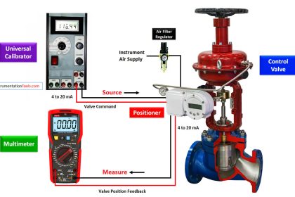
The solution is to fit a positioner to the valve/actuator assembly.

Note: For simplicity, the above examples assume a positioner is not used, and hysteresis is zero.

The formulae used to determine the thrust available to hold a valve on its seat for various valve and actuator combinations are shown in Below Figure.

Where:

A = Effective area of diaphragm

Pmax = Maximum pressure to actuator (normally 1.2 bar)

Smax = Maximum bench setting of spring

Pmin = Minimum pressure to actuator (normally 0 bar)

Smin = Minimum bench setting of spring

The thrust available to close the valve has to provide three functions:

  1. To overcome the fluid differential pressure at the closed position.
  2. To overcome friction in the valve and actuator, primarily at the valve and actuator stem seals.
  3. To provide a sealing load between the valve plug and valve seat to ensure the required degree of tightness.

Control valve manufacturers will normally provide full details of the maximum differential pressures against which their various valve and actuator/spring combinations will operate; the Table in Figure is an example of this data.

Note: When using a positioner, it is necessary to refer to the manufacturer’s literature for the minimum and maximum air pressures.

Control Valve Two Port Characteristics

Article Source : spirax sarco

Articles You May Like :

Control Valve Erosion Problems

Thermostatic valves Principle

Pressure to Current Converter

Mixing or Diverting Valve

Reverse Acting Valves

Don't Miss Our Updates
Be the first to get exclusive content straight to your email.
We promise not to spam you. You can unsubscribe at any time.
Invalid email address
You've successfully subscribed !

Continue Reading

Control Valve Selection Guide
What is Ball Valve ?
Control Valve Parts Questions and Answers
Control Valves Multiple Choice Questions
Self Actuated Pressure Control Valve Functional Testing
Classification of Solenoid Valves
Share This Article
Facebook Whatsapp Whatsapp LinkedIn Copy Link
Share
1 Comment
  • Abdel-rahman Sugar says:
    April 12, 2017 at 10:26 am

    very good article

    Reply

Leave a Reply Cancel reply

Your email address will not be published. Required fields are marked *

Stay Connected

128.3kFollowersLike
69.1kFollowersFollow
208kSubscribersSubscribe
38kFollowersFollow

Categories

Explore More

Different Types of Control Valve Actuators
Components of Shutdown Valve
Difference between Pneumatic, Electrical & Hydraulic Actuators
Control Valve Characteristics
What is Globe Valve ?
Basics of Actuators
Types of Control Valves Noise
Safety Relief Valve Quiz: Test Your Knowledge
ON OFF Valve Preventive Maintenance and Testing Procedure
Lessons Learned from Actuator Passing Incidents

Keep Learning

Quick Exhaust Valve (QEV)

Quick Exhaust and Air Operated Valves in Instrumentation Circuit

Functional Testing of Control Valve Positioners

Functional Testing of Control Valve Positioners

Valve Glossary

Valve Terminology Glossary

Valve Pneumatic Actuator

What is a Pneumatic Actuator ?

3-way-2-position-solenoid-valve-spring-return

Pneumatic Directional Control Valves

Summary of Valve Types Characteristics

Summary of Valve Types Characteristics

Valve Face to Face Dimension

Face to Face Dimension of Control Valve

Pneumatic Valves Questions & Answers

Pneumatic Valves Questions & Answers

Discover More

Infrared Flue Gas Analyser

What is Infrared Flue Gas Analyzer? – Working Principle

Why is White Powder Used in Electrical Cables

Why is White Powder Used in Electrical Cables?

Instrumentation Cyber Security Tips

How to Stop Cyber Attacks on PLC or DCS?

Electronic Devices & Circuits Objective Questions

Electronic Devices & Circuits Quiz – Set 15

Elevator Control

Elevator Control: PLC Program with 5-Second Floor Stops

Valve Seat leakage Test

Valve Seat Leakage Test

Distribution transformer

Different Types of Transformers

Thermocouple Extension Lead Minimizer Circuit

Thermocouple Wires and Extension Lead Issues

Follow US
All rights reserved. Reproduction in whole or in part without written permission is prohibited.
Welcome Back!

Sign in to your account

Username or Email Address
Password

Lost your password?