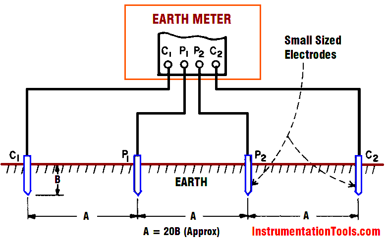
The term “earth resistivity” expressed in ohm-centimeters (abbreviated ohm-cm) is one basic variable affecting resistance to earth of an electrode system. But the actual value of earth resistivity need not be measured to check the electrode earth resistance. Consider other fields where the value of resistivity is measured; also some of the factors affecting it that are of interest in earth testing.
Earth resistivity measurements can be used conveniently for geophysical prospecting — to locate ore bodies, clays, and water-bearing gravel beneath the earth’s surface. The measurement can also be used to determine depth to bed rock and thickness of glacial drift.
Measurements of earth resistivity are useful also for finding the best location and depth for low resistance electrodes. Such studies are made, for example, when a new electrical unit is being constructed; a generating station, substation, transmission tower, or telephone central office.
Finally, earth resistivity may be used to indicate the degree of corrosion to be expected in underground pipelines for water, oil, gas, gasoline, etc. In general, spots where the resistivity values are low tend to increase corrosion. This same kind of information is a good guide for installing cathodic protection.
How Earth Resistivity is Measured
A four-terminal instrument is used to measure earth resistivity. Now, however, you use four small-sized electrodes driven down to the same depth and equal distances apart in a straight line (Fig. 1). Four separate lead wires connect the electrodes to the four terminals on the instrument, as shown. Hence, the name of this test: the four-terminal method.

Fig 1 : Four-terminal method of measuring earth resistivity
Dr. Frank Wenner of the U.S. Bureau of Standards (now NIST) developed the theory behind this test in 1915. He showed that, if the electrode depth (B) is kept small compared to the distance between the electrodes (A)1, the following formula applies:
ρ = 2π AR
where ρ is the average soil resistivity to depth A in ohm-cm, π is the constant 3.1416, A is the distance between the electrodes in cm, and R is the Megger earth tester reading in ohms.
In other words, if the distance A between the electrodes is 4 ft, you obtain the average earth resistivity to a depth of 4 ft as follows:
1. Convert the 4 ft to centimeters to obtain A in the formula: 4 x 12 x 2.54 cm = 122 cm
2. Multiply 2 π A to obtain a constant for a given test setup: 2 x 3.14 x 122 = 766 Now, for example, if your instrument reading is 60 Ω, the earth resistivity would be 60 x 766, or 45,960 ohm-cm.
The conveyor sorting machine is widely used in the packing industries using the PLC program…
Learn the example of flip-flop PLC program for lamps application using the ladder logic to…
In this article, you will learn the STAR DELTA programming using PLC controller to start…
Lube oil consoles of rotary equipment packages in industrial process plants are usually equipped with…
Rotating equipment packages such as pumps, compressors, turbines need the lube oil consoles for their…
This article explains how to blink lights in ladder logic with a detailed explanation video…
View Comments
Dear sir,
here its written A=20B, instead of 2B ?