In any process industry, level measurement is very important for safety and process purpose.
The level can be measured by two methods.
Here we discuss the indirect method and which is using DP transmitter for level measurement.
A Differential pressure transmitter is a common and well-understood technology for liquid level measurement. If the tank is closed or pressurized, a DP measurement must be made to compensate for the vessel pressure.
In closed tank DP level measurement, LP leg is connected to the top of tank.
There are two methods in closed tank DP Level Measurement.
Dry leg method is used in normal close tank where vapor is not condensate and temperature of process is equal to atmospheric.
Wet leg method is used where vapor has a tendency to make the condensate and temperature of process is high or low from the atmospheric .
For DP Transmitter Configuration, we have to find out Zero Level & Span Level. Accordingly we have to configure Lower Range Value (LRV) and Upper Range Value (URV) using HART communicator.
Simply when LP side of the DP transmitter is filled with any gas/air then we call it as Dry Leg & we apply Dry Leg Method for calculations.
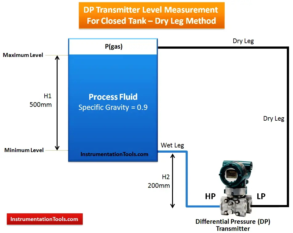
=H2 x specific gravity – 0
= 200 x 0.9 – 0
= 180 mmwc
= (H2+H1) x specific gravity – 0
= (200 + 500) x 0.9 – 0
= 630 mmwc
So, we have to set Lower Range Value (LRV) = 180 mmwc and Upper Range Value (URV) = 630 mmwc in the DP Transmitter using HART communicator.
Simply when LP side of the DP transmitter is filled with liquid then we call it as Wet Leg & we apply Wet Leg Method for calculations.
= H2 x SG1 – Y x SG2
= 200 x 0.9 – 700 x 1.0
= 180 – 700
= – 520 mmwc
= (H2+H1) x SG1 – Y x SG2
= (200 + 500) x 0.9 – 700 x 1.0
= 630 – 700
= -70 mmwc
So, we have to set Lower Range Value (LRV) = -520 mmwc and Upper Range Value (URV) = -70 mmwc in the DP Transmitter using HART communicator.
Rotating equipment packages such as pumps, compressors, turbines need the lube oil consoles for their…
This article explains how to blink lights in ladder logic with a detailed explanation video…
In this article, a simple example will teach you the conversion from Boolean algebra to…
In this article, you will learn the PLC cooking timer example for kitchen automation using…
Learn an example PLC program to control a pump based on level sensors using ladder…
In the PLC timer application for security camera recording, when motion is detected then camera…


View Comments
Dear Sir
I have question, why you neglect the LP side When you do a calculation on a dry leg mode? could you explaine that to me please?
Best regards
Ahmed
when we consider a dry leg, it means that LP side is subject to only Vapor / gas pressure, in the other hand the vapor/gas pressure is applied to both sides (LP and HP). so we don't consider it (ie. the vapor/gas pressure) altogether.
LP is just as compensation for the internal tank pressure, so it does not contribute much during level measurement.
https://mycelectric.com
Horziontal close tank calibration procedure ( DP type transmitter)
capillery type LT
Very useful and explained in a way that can be understood easily.
Dear sir,
how to calculate single liquid LP & HP both side same spesifc graviti (0.838)
H1=90inch
h2=10inch
sg.f=0.838
sg.p=0.838
i have calculate and my answer had came LRV=-67.04 and URV=0 but once i hace feed same value but transmiter showing 167% like.
my transmiter is Husser+Endrees .
Pls let me know ASAP
As per the calculation
LRV = -74.88
URV = 0
In the diagram SG2 is 1.0 and while solving,u have taken the value SG2 as 1.2 ,
Kindly explain
HELLO,
ACCORDING TO MY KNOWLEDGE:
RANGE IS NOTHING BUT URV-LRV
SO,HERE IN THE ABOVE CASE i.e for DP Transmitter Level Measurement for Closed Tank – Wet Leg Method
To Cross Verify the Range: H1*SG1 = 500mm*0.9= 450mm;
Here in the above case at during verification Range:Range = URV – LRV = -210 – (-840) = 630 mmwc the LRV value instead of -660mmwc it is mentioned -840mmwc.I hope that is wrong and we cannot get the range that is to be attained.
you must be wrong.
Y = H1 +H2, what is Y, i have a confusion about it
there are two mistakes in this problem.
1. In diagram you specified a SG2 as 1.0 but in calculation you used as 1.2
2.range valve is URV-LRV= -210-(-660)= -210+660 =450mmwc.
so please verify before posting.. thnak you
Thanks for the notification. Now Updated. Next time we will do re-checks before posting.
In closed tank, wet leg, Y does not equal H1 + H2. Y is visibly longer. Either the diagram was not drawn well enough, and you intended the wet leg to be same as the 100% measurement, or your calcs are wrong, and the dimension for Y would be Y=H1+H2+(some other small height)