Inst ToolsInst ToolsInst Tools
  • Courses
  • Automation
    • PLC
    • Control System
    • Safety System
    • Communication
    • Fire & Gas System
  • Instrumentation
    • Design
    • Pressure
    • Temperature
    • Flow
    • Level
    • Vibration
    • Analyzer
    • Control Valve
    • Switch
    • Calibration
    • Erection & Commissioning
  • Interview
    • Instrumentation
    • Electrical
    • Electronics
    • Practical
  • Q&A
    • Instrumentation
    • Control System
    • Electrical
    • Electronics
    • Analog Electronics
    • Digital Electronics
    • Power Electronics
    • Microprocessor
  • Request
Search
  • Books
  • Software
  • Projects
  • Process
  • Tools
  • Basics
  • Formula
  • Power Plant
  • Root Cause Analysis
  • Electrical Basics
  • Animation
  • Standards
  • 4-20 mA Course
  • Siemens PLC Course
Reading: DP Master System Configuration in PLC
Share
Font ResizerAa
Inst ToolsInst Tools
Font ResizerAa
  • Courses
  • Design
  • PLC
  • Interview
  • Control System
Search
  • Courses
  • Automation
    • PLC
    • Control System
    • Safety System
    • Communication
    • Fire & Gas System
  • Instrumentation
    • Design
    • Pressure
    • Temperature
    • Flow
    • Level
    • Vibration
    • Analyzer
    • Control Valve
    • Switch
    • Calibration
    • Erection & Commissioning
  • Interview
    • Instrumentation
    • Electrical
    • Electronics
    • Practical
  • Q&A
    • Instrumentation
    • Control System
    • Electrical
    • Electronics
    • Analog Electronics
    • Digital Electronics
    • Power Electronics
    • Microprocessor
  • Request
Follow US
All rights reserved. Reproduction in whole or in part without written permission is prohibited.
Inst Tools > Blog > PLC Tutorials > DP Master System Configuration in PLC

DP Master System Configuration in PLC

Last updated: March 4, 2021 2:41 pm
Editorial Staff
PLC Tutorials
No Comments
Share
3 Min Read
SHARE

Write the PLC program for the DP master system configuration in PLC.

Contents
DP Master SystemConfiguration:

DP Master System

DP Master System

In this example, we will configure the DP master system using Simatic manager. For example purpose, we will configure PLC and create a DP master system for the DP communication.

When you configure the DP master system in the software, the software will configure the DP master line automatically. DP slave can be added from the hardware catalog on the DP master line.

DP slave modules or devices can be added as per requirement on the DP master bus. DP master system is used for Profibus communication between the slave device and the master system.

For example purpose, here we have taken S7-300 PLC as a master system and IM module as a slave device.

Configuration:

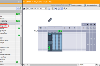
First Configure CPU 315-2 PN/DP from the hardware catalog for DP master system. Once the hardware is created, the DP master system line will be created automatically.

DP Master System Configuration in PLC

By clicking on the DP master bus, the property of the DP master system can be modified as per the requirement as shown in figure 2.

DP master bus

Now right click on DP master and add a new object. From hardware, the catalog selects the DP slave system (for example take IM 153-1) as shown in figure 3.

Profibus DP Master

Double click on the IM module to open DP slave property setting as per the requirement as shown in figure 4.

DP Slave address in Simatic Software

If more IM module in the system, we can add as per the above procedure. As shown in figure 5, you can see one more IM module on the DP master bus.

IM module on the DP master bus

The slot numbering system will be the same as per the S7-300 system. Hence actual I/O modules will start from slot 4 as shown in figure 6.

Siemens Slot numbering system

Note:- This is the simple DP master system configuration, we can use this concept in other examples also.

Author: Bhavesh

If you liked this article, then please subscribe to our YouTube Channel for PLC and SCADA video tutorials.

You can also follow us on Facebook and Twitter to receive daily updates.

Read Next:

Maintenance of PLC’s

Engineering Logic Diagram

STEP 7 PLC programming

PLC Modbus Communication

Comparison Instruction in PLC

Don't Miss Our Updates
Be the first to get exclusive content straight to your email.
We promise not to spam you. You can unsubscribe at any time.
Invalid email address
You've successfully subscribed !

Continue Reading

Actuator Sensor Interface (ASi) Protocol in PLC
Conveyor Sorting System with Color Detection PLC Logic
Design a PLC program for Operational Sequence of Packaging Process
Can a PLC Function Without an HMI or SCADA?
Turbine-Compressor System Architecture
How to Install GSD File in Step 7 PLC using Simatic Manager?
Share This Article
Facebook Whatsapp Whatsapp LinkedIn Copy Link
Share
Leave a Comment

Leave a Reply Cancel reply

Your email address will not be published. Required fields are marked *

Stay Connected

128.3kFollowersLike
69.1kFollowersFollow
210kSubscribersSubscribe
38kFollowersFollow

Categories

Explore More

Wet Contacts and Dry Contacts in PLC Systems
Structured Text PLC Programming for Two-Tanks Level Application
Network Switch Port Allocation Details
Analog Measurement using Ladder Logic
Difference between Compact PLC and Modular PLC
Types of Digital Outputs in PLC
How to Connect PLC with SCADA System via OPC UA?
Tia Portal – Different Instances of Calling a Function Block

Keep Learning

DDE Protocol

What is the DDE Protocol?

Conditional Jump instruction

Jump Instruction in Siemens Tia Portal

Types of Allen Bradley PLC

Types of Allen Bradley PLC

Structured Text in PLC: Parking Information Systems

Structured Text in PLC: Parking Information Systems

Free WinCC SCADA Training Course

Free SCADA Training Course

LIFO Instruction in Allen Bradley PLC Programming

LIFO Instruction in PLC

Online PLC Ladder Logic

Mis-conceptions of PLC Ladder Logic

Scan cycle of a Siemens PLC

OB1 – Main Cyclic Organization Block in TIA Portal

Learn More

Why Grounding

Basics of Grounding

Dip Tube Type Level System

Questions on Dip Tube Type Level System

Diagnosing the Electric Motor Circuit

Diagnosing Electric Motor Circuit

What is an RTD

Components of RTD

Remote User Authentication

Security of Industrial Automation Systems

Modern Industrial Joystick Controls

Installing and Using Modern Industrial Joystick Controls

Top PLC Manufacturers

PLC Brands Software Information

Transformer Operation Under No-Load

Transformer Operation Under No-Load

Menu

  • About
  • Privacy Policy
  • Copyright

Quick Links

  • Learn PLC
  • Helping Hand
  • Part Time Job

YouTube Subscribe

Follow US
All rights reserved. Reproduction in whole or in part without written permission is prohibited.
Welcome Back!

Sign in to your account

Username or Email Address
Password

Lost your password?