How to calibrate the level instrument with DP type Capillary Seal sensors
The use of capillary with fluid inside will the make us to have nice and careful calculation to find what is the range between 0% – 100%. Below is some examples how to find calibrated range for many possible position of the DP type Capillary Seal Level transmitter.
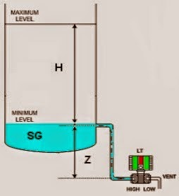
The information given is: H = 100 Inch (Center to Center), Process SG Liquid = 1, h = 50 Inch, SG fill fluid = 1.2. What is the calibrated range? what is the required URV and LRV? for cases below:
1. The first case (atmospheric) is as follows:
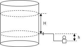
To find a range of 0% -100% level of process fluid with DP Type Level value corresponding instrument is as follows:
0% -> Under these conditions the fill fluid in the capillary has put pressure on the sensor even though the tank is empty. DP received by the sensor is equal to or 50 h InFillFluid InFillFluid which has SG = 1.2. To make it dimensionless InH2O then 50 InFillFluid converted = 50 x 1.2 = 60 InH2O.
100% -> In this condition experienced DP sensor is of (process fluid) + (fill fluid). The pressure sensor is received (100 InH2O) + (60 InH2O) = 160 InH2O.
Calibrated range is 60 InH2O to 160 InH2O.
2. The second case (atmospheric) is as follows:
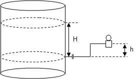
To find a range of 0% -100% level of process fluid with DP Type Level value corresponding instrument is as follows:
0% -> Under conditions of process liquid tank is empty, the sensor will receive the DP negative because it is higher than the tapping point kapilary (Zero Elevation). Is this a vacuum condition because of pressure disuck or aspirated? I do not think so. DP nagative as head h and the level of process liquid H will push each other in opposite directions. The higher level of process liquid, the higher the pressure that is otherwise against the head h. H Head pressure is 50 InFillFluid = 60 InH2O but negative or – 60 InH2O.
100% -> In this condition experienced DP sensor is on the process pressure fluid- pressure fluid fill. The pressure sensor is received (100 InH2O) – (60 InH2O) = 40 InH2O.
InH2O calibrated range is -60 to 40 InH2O.
3. The case of the third (closed tank roof) is as follows:
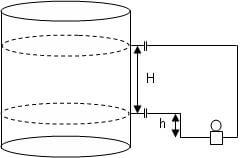
To find a range of 0% -100% level of process fluid with DP Type Level value corresponding instrument is as follows:
0% -> Under these conditions the fill fluid in the capillary has put pressure on the sensor from both sides even though the tank is empty. Pressure received by the sensors of Hi -side (tapping point below) amounted h InFillFluid or 50 InFillFluid which has SG = 1.2. To make it dimensionless InH2O then 50 InFillFluid converted into 50 x 1.2 = 60 InH2O of the Hi-side. Lo received pressure sensor -side(tapping point above) is equal to H + h InFillFluid or 150 InFillFluid which has SG = 1.2. To make it dimensionless InH2O then 150 InFillFluid converted into 150 x 1.2 = 180 InH2O. Wah both sides put pressure yes yes although the tank is empty? DP when the level of 0% is obtained by subtracting the pressure (Hi-side) – (Lo-side). Level 0% = (60 InH2O) – (180 InH2O) = – 120 InH2O. You know if, in the tank already contained gas or vapor then with the Hi and Lo-side tapping point then by subtracting each method (remember DP = difference) is the pressure of gas / vapor on the surface of the liquid will cancel out all by itself.
100% -> In this condition experienced DP sensor is of (process fluid pressure) + (Hi fill fluid pressure) – (Lo pressure fluid fill). DP received sensor is (100 InH2O) + (60 InH2O) – (180 InH2O) = -20 InH2O. Gas or Vapor pressure above the liquid does not need to be taken into account because it will cancel out the Hi and Lo side by itself.
Range is calibrated -120 to -20 InH2O InH2O.
4. The case of the four (closed tank roof) is as follows:
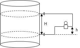
To find a range of 0% -100% level of process fluid with DP Type Level value corresponding instrument is as follows:
0% -> Under these conditions the fill fluid in the capillary has put pressure on the sensor from both sides even though the tank is empty. Pressure received by the sensors of Hi -side (tapping point below) amounted h InFillFluid or 50 InFillFluid which has SG = 1.2, but negative. To make it dimensionless InH2O then converted InFillFluid -50 to -50 x 1.2 = – 60 InH2O of the Hi-side. Lo received pressure sensor -side (tapping point above) amounted Hh InFillFluid or 50 InFillFluid which has SG = 1.2. To make it dimensionless InH2O then 50 InFillFluid converted into 50 x 1.2 = 60 InH2O. Wah both sides put pressure yes yes although the tank is empty? DP when the level of 0% is obtained by subtracting the pressure (Hi-side) – (Lo-side). DP on Level 0% = (-60 InH2O) – (60 InH2O) = – 120 InH2O. You know if, in the tank already contained gas or vapor then with the Hi and Lo-side tapping point then by subtracting each method (remember DP = difference) is the pressure of gas / vapor on the surface of the liquid will cancel out all by itself.
100% -> In this condition experienced DP sensor is on (pressure process fluid) – (Hi fill fluid pressure) – (Lo pressure fluid fill). DP received sensor is (100 InH2O) – (60 InH2O) – (60 InH2O) = -20InH2O. Gas or Vapor pressure above the liquid does not need to be taken into account because it will cancel out the Hi and Lo side by itself.
Range is calibrated -120 to -20 InH2O InH2O.
Also Read: Level Indicators Working Principle


Good
Thanks for your marvelous posting! I definitely enjoyed reading it, you may be a great author.I will ensure that I bookmark your blog and will come back in the foreseeable
future. I want to encourage yourself to continue your great work. Thanks
How to calibrate a temperature transmitter
Hi Bharadwaj. How are you?
A Das
I really enjoyed I even liked your page in face book…good inputs
Hi,
I tend to disagree with you for the part that the vapour pressure of a closed tank will tend to cancel each other.
I have a process condition where the liquid density is 0.85 and vapour density is significantly high which is 0.28. In other words, it acts as if it is acting like a interface liquid level, even though it is just a liquid level.
Could you suggest a recommended way to calibrate it for the same dimensions in your example?
Much appreciated.
Ravi