There are many control circuits used in the industry. Control the double-acting pneumatic cylinder position by using a 5/2 direction control valve.
Our objective is to learn directional control valve function and pneumatic cylinder control. So, control the double-acting pneumatic cylinder by using a normal electric circuit and use the programmable logic controller to control the double-acting cylinder.
Double Acting Cylinder
Solution:
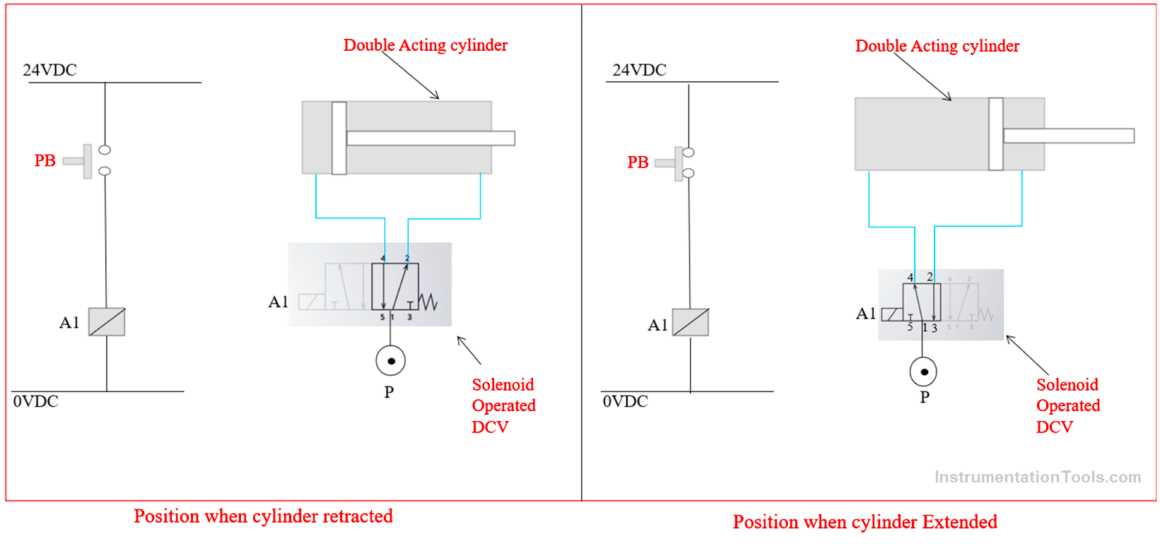
As shown in the figure we can learn the workings of the 5/2 direction control valve and we can see the function of the double-acting cylinder. For example, we considered here double-acting cylinder operation, and we can operate this double-acting pneumatic cylinder by using 5/2 solenoid-operated direction control.
Here we took two position explanations for the application. In the first condition, we have taken a pneumatic double-acting cylinder retraced condition so that this pneumatic cylinder will remain in a close position.
Let’s understand the mechanism behind the operation, here all operations are happening by the single solenoid-operated direction control valve. As shown in the figure we can see the retracted position of the pneumatic-operated double-acting cylinder.
In this operation, we are using a single solenoid-operated direction control valve, so we have to use the electrical circuit to represent the electrical operation of the solenoid coil in the single solenoid-operated direction control valve (A1).
Here we are using a 5/2 single solenoid-operated direction control valve, so it has 5 ports and 2 positions. Here in the figure, we can see five ports of the single solenoid-operated direction control valve which is shown by numbers 1,2,3,4, and 5.
Generally, 1 is used for the Air in, and 3, and 5 are used for the exhaust of the air which is flowing from the double-acting pneumatic cylinder. And 4,2 are the ports that are connected to the double-acting pneumatic cylinder.
Here our purpose is to understand the working of the direct operation of an acting pneumatic cylinder. So, we are operating the solenoid coil directly via a push button, in the initial condition coil is not in operated condition pneumatic air will flow from the 1 to 2 port and it will push the cylinder in close condition.
The other side cylinder air will exhaust from exhaust port 5 so in the figure you can see the flow from the 4 to 5 ports.
Now we will study and learn another position of the double-acting pneumatic cylinder.
PLC Program
Here we can write a PLC program for this application for explanation purposes. We will make a simple programmable Logic Controller Program to understand the application.
List of Inputs/Outputs
List of Inputs
X0: PB
List of Outputs
Y0: Solenoid
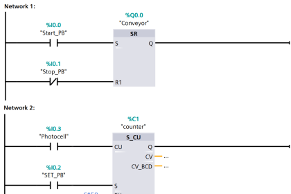
Ladder Logic Diagram
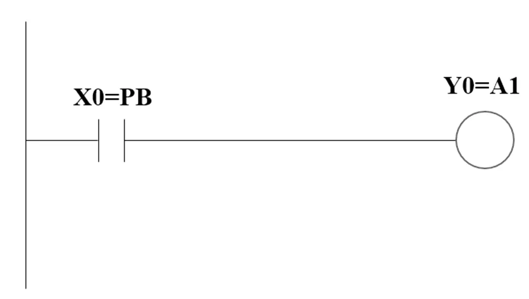
Program Explained
In the first rung, we used NO contact of the push button (X0) so the Cylinder forward (Y0) output could be operated with the push button (X0). Hence once you press the push button the output will give a signal to the solenoid A 1 and due to the mechanism direction control valve spooler will move and it will change the direction of the air.
As shown in the figure, we can see a simple ladder diagram for the application. In this, we can connect the NO push button with the programmable logic controller. Solenoid solenoid-operated direction control valve can be connected to the programmable logic controller output. So, once you press the push button, the programmable logic controller generates the output, and it will operate the solenoid.
If you liked this article, then please subscribe to our YouTube Channel for Electrical, Electronics, Instrumentation, PLC, and SCADA video tutorials.
You can also follow us on Facebook and Twitter to receive daily updates.
Read Next:
- Basics of PLC Programming
- Fail-Close Valve Advantages and Disadvantages
- Digital Control Valves Principle Applications
- PLC Programming Example using Switches
- Single-acting Pneumatic Cylinder Operation