The current consumption of an industrial sensor is a very important consideration. Knowing the current consumption of all your devices on a machine allows you to size wire properly and pick the right power supply for the application.
There are two specifications on a data sheet that are worth looking at. The first is the no-load supply current and the second is the load current.
No-Load Supply Current
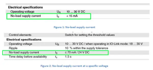
When sizing a power supply, this is the most important specification to look at. No-load supply current is the amount of current that a device consumes when the device is just sitting there. This current is consumed no matter if there is a load attached to the output or not. In Figure 1, you see that this sensor has a current consumption of 15 mA or less. This value is the current consumption maximum over all voltage and temperature ranges. Sometimes the current consumption is specified at a specific voltage like in Figure 2.
Load Current
This specification is the most misunderstood. Load current simply tells the user how much current the industrial sensor can supply to a load. It is not the amount of current that a sensor will supply to a load. You really need to know what load is connected to the sensor to know how to size the power supply. 95% of all sensors used today are connected to very low current I/O cards. An I/O card has a fixed load current and will consume between 3 mA and 9 mA at 24 VDC depending on the hardware design.
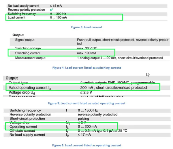
This current is consumed only when the sensor is switched and the output turns on. Needless to say, you always assume, when sizing a power supply, that all sensors are on all the time. You always plan for a worst-case scenario and you want a safety margin designed into your system. This specification of load current has many names in a catalog or data sheet and they include Load Current (Figure 3), Switching Current (Figure 4), Rated Operating Current (Figure 5), and Operating Current (Figure 6).
Just make sure that the load current rating from the data sheet of the sensor is greater than the current consumption of the input card.
For example, an input module has an input current of 9 mA. If the allowed maximum load current of the sensor is 100 mA, which is much larger than 9 mA, the sensor will function properly and the sensor will not be overloaded.
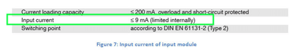
The total current consumption of the sensor is the no-load supply current of the sensor plus the input current of the module or I/O card. For example, if the no-load supply current is 15 mA (Figure 1) and the input current is 9 mA (Figure 7), then the total current consumed is 15 mA + 9 mA, which equals 24 mA. This is the number you would use to size your power supply for that sensor.
Conclusion
Sometimes the data sheets give you more information than you really need. Use the no-load supply current and the current consumption of the I/O module to come up with the total current consumption of your sensor. Then, as an extra check, make sure that the allowed maximum load current of the sensor is larger than the input current on the module or I/O card. Now that you have the current consumption for one sensor, do this for all sensors on your entire machine. You can now size the cable and power supplies properly.
Source : P & F


Thank you so much for sharing your valuable knowledge..