Inst ToolsInst ToolsInst Tools
  • Courses
  • Automation
    • PLC
    • Control System
    • Safety System
    • Communication
    • Fire & Gas System
  • Instrumentation
    • Design
    • Pressure
    • Temperature
    • Flow
    • Level
    • Vibration
    • Analyzer
    • Control Valve
    • Switch
    • Calibration
    • Erection & Commissioning
  • Interview
    • Instrumentation
    • Electrical
    • Electronics
    • Practical
  • Q&A
    • Instrumentation
    • Control System
    • Electrical
    • Electronics
    • Analog Electronics
    • Digital Electronics
    • Power Electronics
    • Microprocessor
  • Request
Search
  • Books
  • Software
  • Projects
  • Process
  • Tools
  • Basics
  • Formula
  • Power Plant
  • Root Cause Analysis
  • Electrical Basics
  • Animation
  • Standards
  • 4-20 mA Course
  • Siemens PLC Course
Reading: Difference between Signal Cables and Control Cables
Share
Notification Show More
Font ResizerAa
Inst ToolsInst Tools
Font ResizerAa
  • Courses
  • Design
  • PLC
  • Interview
  • Control System
Search
  • Courses
  • Automation
    • PLC
    • Control System
    • Safety System
    • Communication
    • Fire & Gas System
  • Instrumentation
    • Design
    • Pressure
    • Temperature
    • Flow
    • Level
    • Vibration
    • Analyzer
    • Control Valve
    • Switch
    • Calibration
    • Erection & Commissioning
  • Interview
    • Instrumentation
    • Electrical
    • Electronics
    • Practical
  • Q&A
    • Instrumentation
    • Control System
    • Electrical
    • Electronics
    • Analog Electronics
    • Digital Electronics
    • Power Electronics
    • Microprocessor
  • Request
Follow US
All rights reserved. Reproduction in whole or in part without written permission is prohibited.
Inst Tools > Blog > Electrical Basics > Difference between Signal Cables and Control Cables

Difference between Signal Cables and Control Cables

Signal cables are used for data or signal transmission while control cables are used to control devices to the machinery they control.

Last updated: July 24, 2023 10:35 am
Editorial Staff
Electrical Basics PLC Tutorials
1 Comment
Share
4 Min Read
SHARE

In industrial automation systems, both signal cables and control cables carry information between the control system and field devices but have different purposes and characteristics.

Contents
Signal CablesControl CablesDifference between Signal Cables and Control Cables

Signal Cables

Signal cables are used to carry low-level electronic signals between devices or within a device. These can include data signals, such as Ethernet or Fieldbus communication, or they can be low-voltage analog or digital signals, like 4-20mA current loops, or 0-10V signals. The main function of these cables is to relay information, not to deliver power or actuate machinery.

Signal cables typically have several characteristics designed to maintain the integrity of the signals they carry, including:

  • Shielding: To protect against electromagnetic interference (EMI) which could degrade the signal.
  • Twisted pairs: To reduce the influence of external interference and to minimize cross-talk between signals in different pairs in the same cable.
  • Lower current carrying capacity: These cables are designed for signal transmission rather than power delivery.
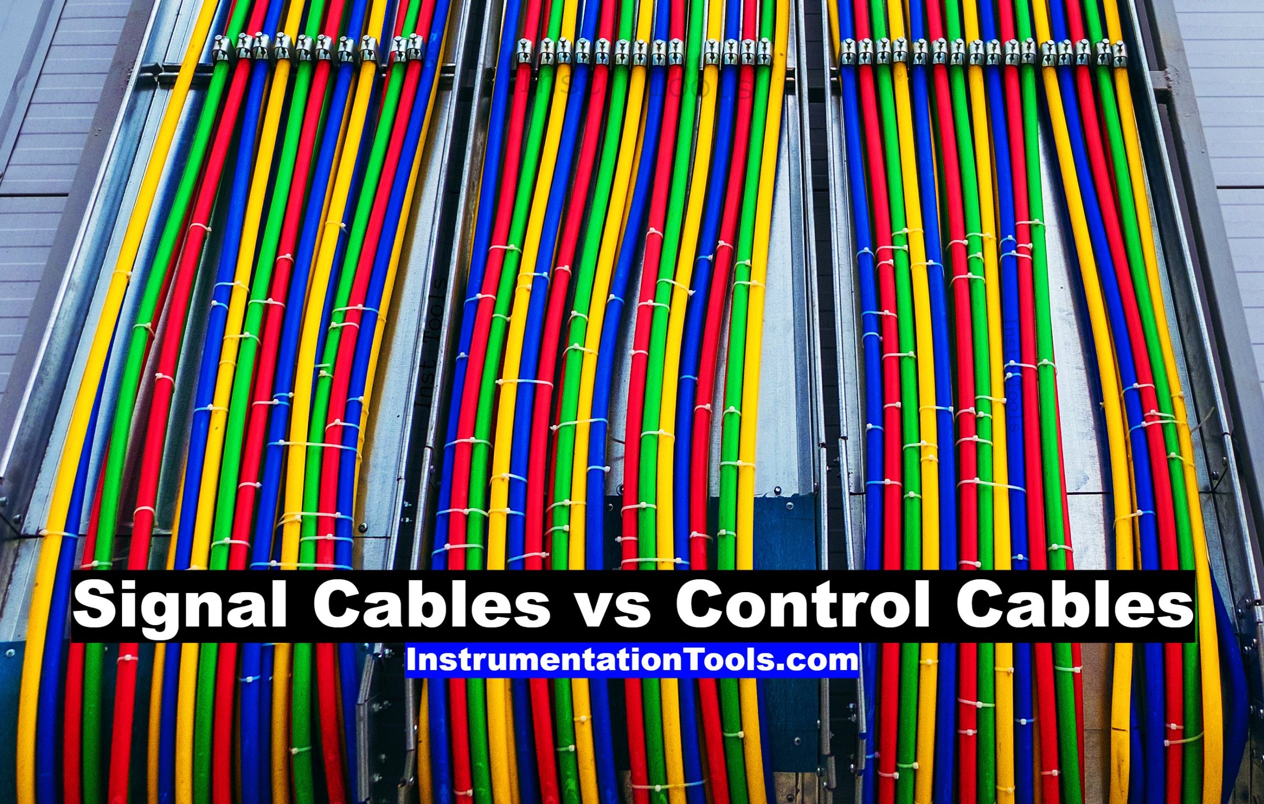
Difference between Signal Cables and Control Cables

Control Cables

Control cables are used in industrial automation to connect control devices like PLC (Programmable Logic Controllers) to the components they control, such as motors, valves, actuators, etc. These cables can carry higher currents and voltages, as they are often used to deliver the power that actuates a device or machine.

Control cables usually have these features:

  • Higher current carrying capacity: These cables are designed to carry the current needed to control machinery or devices.
  • Can be shielded or unshielded: Depending on the environment and the specific requirements of the application, control cables may also be shielded to protect against EMI.
  • Might have multiple conductors: Control cables often have multiple conductors to allow for multiple control or power connections to be made with a single cable.

The main difference between signal and control cables lies in their purpose: signal cables are used for data or signal transmission while control cables are used to connect control devices to the machinery they control, typically delivering the power to actuate those machines.

Difference between Signal Cables and Control Cables

In the below table, we discussed the comparison between signal and control cables.

DetailsSignal CablesControl Cables
PurposeTransmit low-level electronic signals or data.Connect control devices to machines they control.
Type of ConnectionConnect devices for data or signal transmission.Connect devices for control or power delivery.
Current Carrying CapacityLower, since they are for signal transmission.Higher, since they are used to power or control devices.
ShieldingTypically shielded to protect against EMI.Can be either shielded or unshielded.
Conductor ConfigurationOften uses twisted pairs to reduce interference.May have multiple conductors for multiple connections.

If you liked this article, then please subscribe to our YouTube Channel for Electrical, Electronics, Instrumentation, PLC, and SCADA video tutorials.

You can also follow us on Facebook and Twitter to receive daily updates.

Read Next:

  • Single Core and Multi-Core Cables
  • Difference Between HV and LV Cables
  • Types of Cables in Industrial Automation
  • Instrumentation Cables Testing Steps
  • Flame Resistant and Retardant Cables
  • Materials in Instrumentation Cables
Don't Miss Our Updates
Be the first to get exclusive content straight to your email.
We promise not to spam you. You can unsubscribe at any time.
Invalid email address
You've successfully subscribed !

Continue Reading

Emergency Stop Switch Spurious Trip
PLC Programming Best Practices and Tips
What is PLC Redundancy?
PLC Instruction List for Motor Reverse and Forward Direction
How to Design an Effective HMI? – Human Machine Interface
How Modbus is used in Industrial Networks?
Share This Article
Facebook Whatsapp Whatsapp LinkedIn Copy Link
Share
1 Comment
  • Joseph Kevin Raju says:
    December 4, 2023 at 1:01 pm

    Hi,

    I believe there is a mistake in the terminologies used and the explanations provided. Control i.e. Process Control Cables are used to communicate signals – be they analog or digital or Modbus or F.O. from DCS or PLC or even an LCP to or from instruments, analyzers, Indicators, Recorders etc.

    Electrical cables (usually LV) on the other hand deliver power from the source, which can be an MCC or PDB to motors, pumps, valves etc. Instruments are usually loop-powered, eliminating the need for a separate power supply transferred through a separate set of cables.

    I believe an article on Digital vs Analog control cables will be useful, as this platform is mainly focused on the Instrumentation side of things.

    Thanks.

    Reply

Leave a Reply Cancel reply

Your email address will not be published. Required fields are marked *

Stay Connected

128.3kFollowersLike
69.1kFollowersFollow
210kSubscribersSubscribe
38kFollowersFollow

Categories

Explore More

Do’s and Don’ts in PLC
Surface Grinding Process using PLC Program
What is a Floating License? – Automation Software Systems
Circuit Breaker Making Capacity
Can a PLC Function Without an HMI or SCADA?
Allen Bradley Bitwise Logical Operations
Normally-open and Normally-closed Switch Contacts
How Engineers Effectively do Problem-solve and Troubleshoot?

Keep Learning

PLC Programming for Level Switches

PLC Programming using Level Switches

Counter Count Down Bit

Down Counter PLC Program

Automation Engineers Interview Questions

Industrial Automation Engineers Interview Questions

PLC automation timers and counters

Medium-Level PLC Exercise for Students in Automation

PLC Emergency Stop Example Program

PLC Emergency Stop Example Program

Difference Between Open Circuit and Close Circuit

Difference Between Open Circuit and Close Circuit

Concept of Interlocking in PLC

Concept of Interlocking in PLC

Types of Tripping Protection in MCCB

Types of Tripping Protection in MCCB

Learn More

R R-C Firing Circuits Disadvantages

R R-C Firing Circuits Disadvantages

Direct & reverse actions control valve

Direct Acting Control Valves & Reverse Acting Control Valves

VFD Block Diagram

What is a VFD? – Theory, Advantages, Disadvantages

Valve Non-rising Stems

Valve Functions and Basic Parts of Valve

Difference Between Passive and Active Fire Protection

Active and Passive Fire Protection

Safety Questions and Answers

Safety Questions and Answers

PLC Programming Limit Switch

PLC Programming Example using Limit Switch

Factors to Consider When Choosing Power Tools

Factors to Consider When Choosing Power Tools

Menu

  • About
  • Privacy Policy
  • Copyright

Quick Links

  • Learn PLC
  • Helping Hand
  • Part Time Job

YouTube Subscribe

Follow US
All rights reserved. Reproduction in whole or in part without written permission is prohibited.
Welcome Back!

Sign in to your account

Username or Email Address
Password

Lost your password?