LVDT and RVDT is a passive transducer. LVDT stands for linear voltage differential transformer, whereas RVDT stands for rotary voltage differential transformer.
It is an inductive transducer converts displacement into a change in inductance of the coil.
LVDT
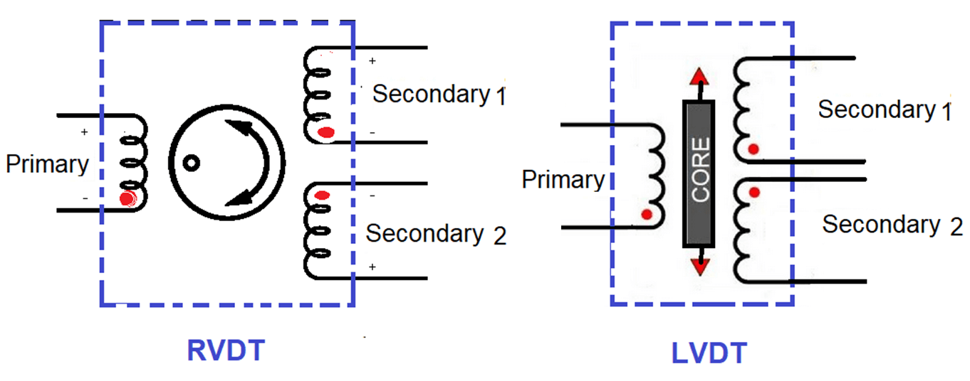
The Linear voltage differential transformer converts linear displacement into an electrical signal. It comprises one primary and two secondary coil windings. Both windings are an equal number of turns and they are connected in series to each other. The primary winding is placed as opposed to the two secondary windings as shown in the below figure.
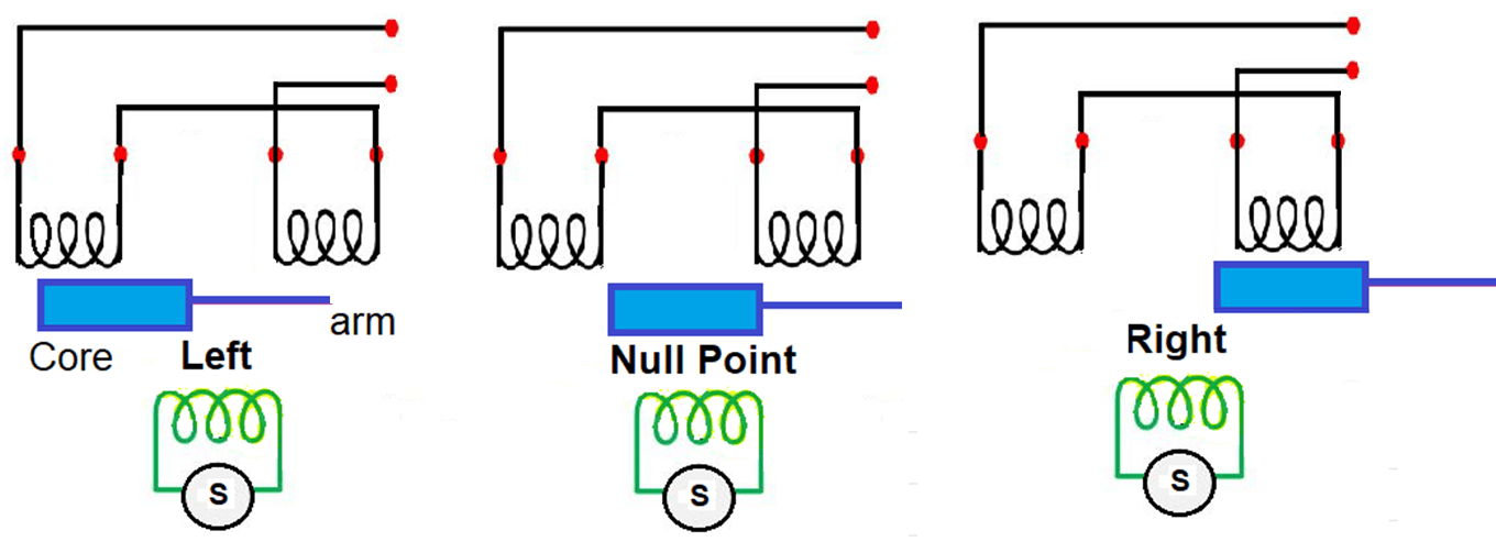
The primary winding is excited by the alternating current, the core is placed inside of it. The alternating current induces flux in primary and by mutual induction, the flux is induced in secondary.
Induced flux changes in secondary windings as per the movement of the iron core at the null position, left-hand side, and right side.
RVDT
The rotary variable differential transformer used for the measurement of angular displacement. It converts angular displacement into an alternating electrical signal. The construction of RVDT and LVDT are similar, in both cases one primary winding and two secondary windings are used.
The only difference is that core in RVDT is cam-shaped and rotated inside the windings through a shaft attached to it. The core is rotated in a clockwise and anti-clockwise rotation with respect to a NULL position.
When the core is in the null position, the output voltage is zero and because the voltages induced in both secondary windings S1 and S2 are equal and opposite direction. If any angular displacement is measured to be applied to the core, differential voltages get developed across the windings S1 and S2.
When the core is rotated in a clockwise direction, the voltage gets an increase. Voltages get decreased when rotated in an anti-clockwise direction.
Difference between LVDT and RVDT
- LVDT – converts linear displacements into alternating electrical signals.
- RVDT – converts angular displacements into alternating electrical signals.
- LVDT – core is in linear motion.
- RVDT – core is circular.
- LVDT – used for converting linear motions into electrical signals.
- RVDT – used for converting rotary motions into electrical signals.
- LVDT – Linear over displacement up to several hundred millimeters long.
- RVDT – It operates 360 degrees but the range of linear operation is + or – 40 degrees.
- LVDT – Core shape is rectangular.
- RVDT – Core is cam-shaped.
- LVDT – Input voltage range from 1V to 24 V RMS.
- RVDT – Upto 3 V RMS.
- LVDT – Sensitivity 2.3 mV/V/ degree of rotation.
- RVDT – Sensitivity 2 to 3 mV/ V/ degree of rotation.
- LVDT – Operating frequency range from 50 Hz to 20 kHz.
- RVDT – Operating frequency range from 400 Hz to 20 kHz.
- LVDT – Its application in measuring force, pressure, weight, displacement.
- RVDT – Used in various precision controlling applications such as turbine operation, radar systems, etc.
Reference: MECHATRONICS By M.D Singh J.P Joshi.
Read Next:
- History of Instrument Signals
- Compare Fieldbus & 4-20mA
- Why 4-20 mA Popular?
- What is Live Zero in 4-20 mA?
- Loop Checking of Transmitters









THIS IS GREAT. KEEP UP THE GOOD WORK.
GOD BLESS YOU SIR
Good