Inst ToolsInst ToolsInst Tools
  • Courses
  • Automation
    • PLC
    • Control System
    • Safety System
    • Communication
    • Fire & Gas System
  • Instrumentation
    • Design
    • Pressure
    • Temperature
    • Flow
    • Level
    • Vibration
    • Analyzer
    • Control Valve
    • Switch
    • Calibration
    • Erection & Commissioning
  • Interview
    • Instrumentation
    • Electrical
    • Electronics
    • Practical
  • Q&A
    • Instrumentation
    • Control System
    • Electrical
    • Electronics
    • Analog Electronics
    • Digital Electronics
    • Power Electronics
    • Microprocessor
Search
  • Books
  • Software
  • Projects
  • Process
  • Tools
  • Basics
  • Formula
  • Power Plant
  • Root Cause Analysis
  • Electrical Basics
  • Animation
  • Standards
  • 4-20 mA Course
  • Siemens PLC Course
Reading: Difference Between Core and Shell Transformers
Share
Notification Show More
Font ResizerAa
Inst ToolsInst Tools
Font ResizerAa
  • Courses
  • Design
  • PLC
  • Interview
  • Control System
Search
  • Courses
  • Automation
    • PLC
    • Control System
    • Safety System
    • Communication
    • Fire & Gas System
  • Instrumentation
    • Design
    • Pressure
    • Temperature
    • Flow
    • Level
    • Vibration
    • Analyzer
    • Control Valve
    • Switch
    • Calibration
    • Erection & Commissioning
  • Interview
    • Instrumentation
    • Electrical
    • Electronics
    • Practical
  • Q&A
    • Instrumentation
    • Control System
    • Electrical
    • Electronics
    • Analog Electronics
    • Digital Electronics
    • Power Electronics
    • Microprocessor
Follow US
All rights reserved. Reproduction in whole or in part without written permission is prohibited.
Inst Tools > Blog > Electrical Basics > Difference Between Core and Shell Transformers

Difference Between Core and Shell Transformers

In this post, we will learn the difference between core and shell transformers used in electrical engineering industries.

Last updated: September 28, 2022 3:42 pm
Viral Nagda
Electrical Basics
No Comments
Share
5 Min Read
SHARE

In this post, we will learn the difference between core and shell transformers used in electrical engineering industries.

Contents
What is a Core Type Transformer?What is a Shell Type Transformer?Difference between Core and Shell Transformers

A transformer is an electrical device which is used to change voltage range; either increasing it to a certain level or decreasing it to a certain level. It is one of the most basic components used in an electrical network.

Voltage conversion is necessary because you cannot always apply the same input voltage to any device. Every instrument has it’s own set of power requirement and it varies from instrument to instrument.

Now, based on construction, two types of transformers are generally used – core and shell. In this post, we will see the difference between core type and shell type transformers.

What is a Core Type Transformer?

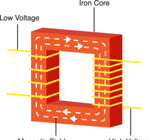
A core type transformer is the one in which the primary and secondary windings encircle the core of the transformer. Refer to the below image.

What is a Core Type Transformer

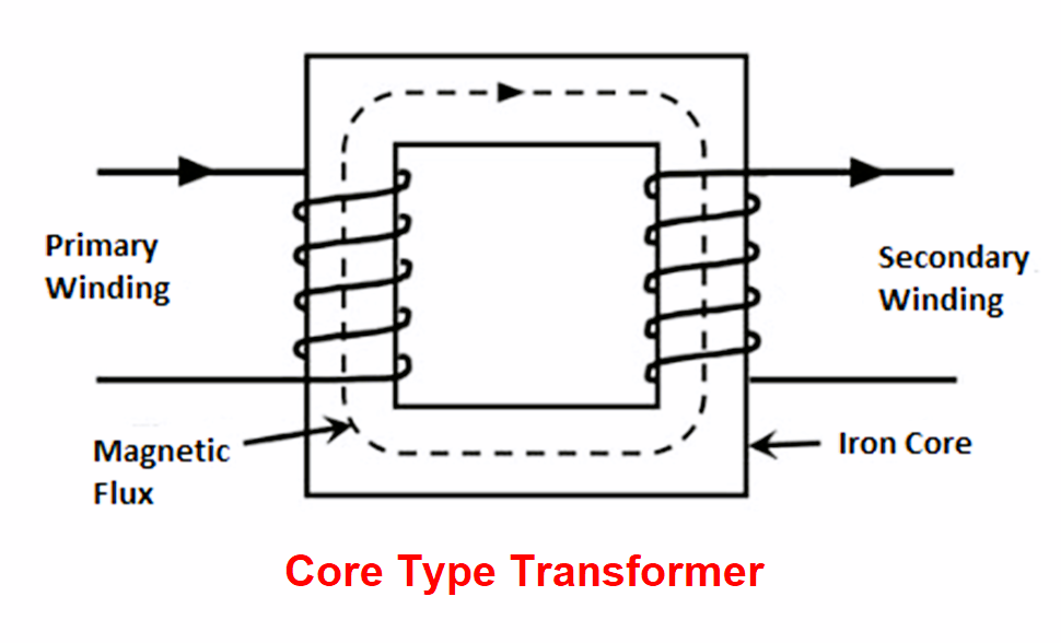
As you know, a transformer has two types of windings – primary and secondary. Voltage is transferred from primary to secondary windings through magnetic flux.

The windings in this figure are mounted on the core of the transformer. Core is the metallic layer which conducts magnetic field and can also be termed as the main body of the transformer.

So, in this type of transformer, the windings are surrounding the core. That is why, they are called as core type transformer. The part where the winding is done is also known as the limb. Both the windings are mounted on separate limbs of the core. As you can see, there is only single flux path in the circuit.

Also, it is to be noted that two types of windings are present on each of the primary and secondary ones – low voltage (LV) and high voltage (HV). In the below image, green one is LV winding and red one is HV winding.

Transformer LV winding and HV winding

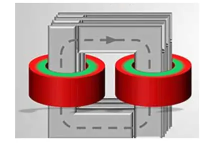
LV winding is placed near the core and HV winding is overlapped on the LV winding. As you can see, there is not a single core; but multiple layers of core. They are called as laminations.

What is a Shell Type Transformer?

A shell type transformer is the one in which the core of the transformer encircles the windings. Refer to the below image.

What is a Shell Type Transformer

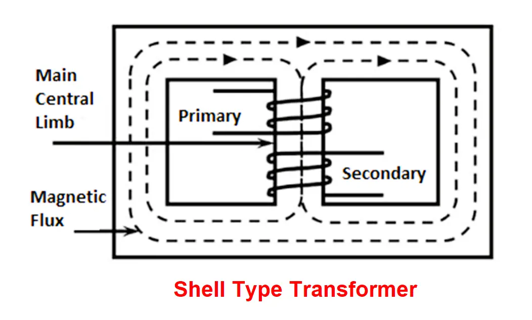
In this type of transformer, the core is surrounding the primary and secondary windings. That is why, they are called as shell type transformer.

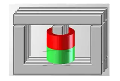
Both the windings are wound on a central limb of the core. As you can see, there is two flux paths in the circuit. The central limb carries the whole magnetic flux; and the other two side limbs carry half of the flux.

HV and LV winding mounting is same as discussed earlier in core type transformers. The red winding in the second image below is primary and the green winding is secondary winding.

Shell Transformer

Difference between Core and Shell Transformers

The following are the key differences between core and shell transformers.

  • The main general difference is that in core transformer, the windings surround the core; whereas in shell transformer, the core surrounds the winding.
  • Core type is more compact and smaller in size as compared to a shell type.
  • Winding protection is more safer in shell type than in core type, due to it’s construction.
  • The cross section area of core type is rectangular, but that in shell type is square shape.
  • Core type has two limbs as compared to shell type which has three limbs.
  • Core type has only one magnetic flux path as compared to shell type which has two paths.
  • Core type has more losses as compared to shell type, so output is better in shell type.
  • Due to separate limbs for the windings, core type is easy to repair and troubleshoot as compared to shell type.
  • The mechanical strength of core type is less as compared to shell type.
  • Core type is used for high voltage applications like autotransformers and power transformers. Shell type is used for low voltage applications like transformers in an electronic circuit.
  • Cooling is better in core type, because the windings are directly exposed to atmosphere, as compared to shell type ones.

In this way, we understand the difference between core type and shell type transformers.

Don't Miss Our Updates
Be the first to get exclusive content straight to your email.
We promise not to spam you. You can unsubscribe at any time.
Invalid email address
You've successfully subscribed !

Continue Reading

Types of Electrical Loads
What is an Electrical Drive? Types, Advantages, Disadvantages
What is an Armoured Cable? Classification of Cables
Difference Between Single Core and Multi-Core Cables
4-20mA Linear Conversion Calculation for VFD Drive (Formula)
Advantages of Valve Regulated Lead Acid (VRLA) Batteries
Share This Article
Facebook Whatsapp Whatsapp LinkedIn Copy Link
Share
Leave a Comment

Leave a Reply Cancel reply

Your email address will not be published. Required fields are marked *

Stay Connected

128.3kFollowersLike
69.1kFollowersFollow
208kSubscribersSubscribe
38kFollowersFollow

Categories

Explore More

Electrical Terminology
How Do Air Compressor Filters Clean and Protect the System?
Why CT Secondary Should Never Be Kept Open?
Various Control Methods in Servo Motor Drives
How does a Lead Acid Battery Work?
Difference Between NEMA and IEC Motors?
What is a Protective Relay? Principle, Advantages, Applications
Circuit Breaker Making Capacity

Keep Learning

Working of Stepper Motor

Types of Stepper Motors

Totally Enclosed Fan Cooled (TEFC) Motor

Totally Enclosed Fan Cooled (TEFC) Motors Rampant Winding Burnouts

Induction Motor Operation

Induction Motor Over and Under Voltage Problems

Constant Torque Load of Electrical Motor

Types of Motor Loads – Constant & Variable Torque, Horsepower

Electrical Motor Model number and serial number

How to Read the Nameplate of a Motor?

Difference Between Alternator and Generator

Difference Between Alternator and Generator?

Switched Mode Power Supply (SMPS)

How does SMPS Works? – Switched Mode Power Supply

automatic changeover switch explained

Automatic Transfer Switch – Electrical Circuit, Operation, Video

Learn More

Free Download PLC Simulator using Excel

PLC Simulator using Excel

What is a Bus Coupler in Electrical Panel

What is a Bus Coupler in Electrical Panel?

Sinking and Sourcing Devices Operation

PLC Sinking and Sourcing Explanation

How to choose between PLC and DCS Systems

How to choose between PLC and DCS Systems ?

Automating Car Parking with Advanced PLC Logic

Complex Car Parking Logic in XG5000 LS Electric PLC

Power Systems Questions & Answers

Power Systems MCQ Series 16

Electrical Machines Questions and Answers

Power Flow Through an Inductive Impedance Questions

Ultrasonic Flow meters Working Animation

Ultrasonic Flow Meters Animation

Follow US
All rights reserved. Reproduction in whole or in part without written permission is prohibited.
Welcome Back!

Sign in to your account

Username or Email Address
Password

Lost your password?