Superheated steam provides an excellent source of energy for mechanical power generation. However, in many instances, steam at greatly reduced temperatures, near saturation, proves a more desirable commodity. This is the case for most heat–transfer applications.
Precise temperature control is needed to improve heating efficiency; eliminate unintentional superheat in throttling processes; or to protect downstream product and/or equipment from heat related damage. One method to reduce temperature is the installation of a desuperheater.
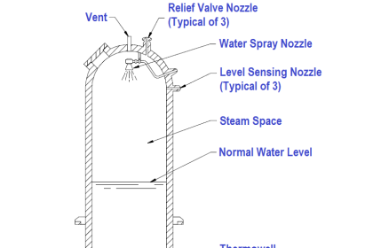
A desuperheater injects a controlled, predetermined amount of water into a steam flow to lower the temperature of the steam. To achieve this efficiently, the desuperheater must be designed and selected correctly for the application.
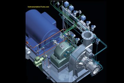
Desuperheater
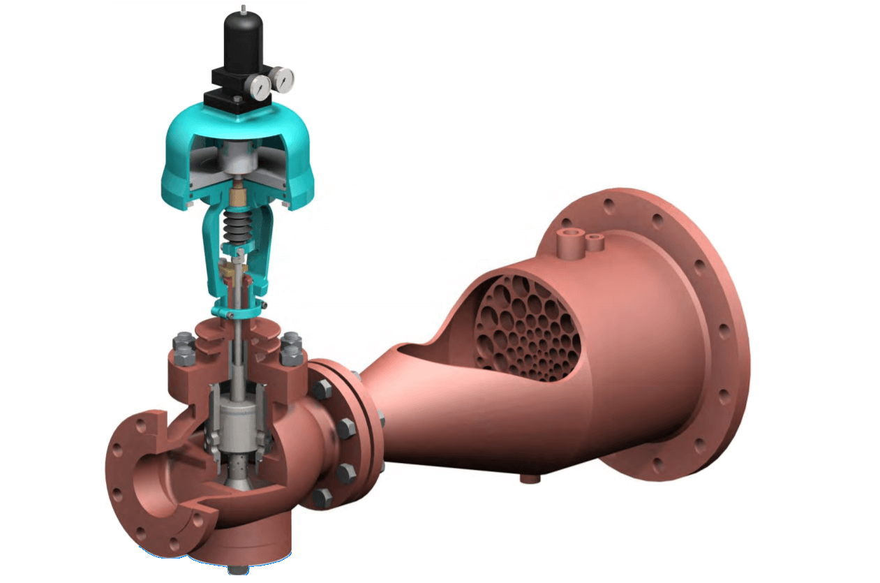
Image Courtesy: Auldvalves
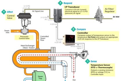
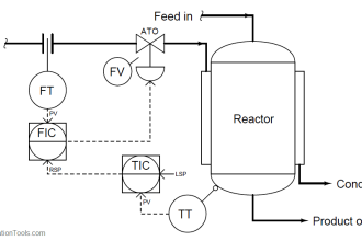
Although it can appear simplistic in design, the desuperheater must integrate with a wide variety of complex thermal and flow dynamic variables to be effective. The control of the water quantity, and thus the steam temperature, uses a temperature control loop.
This loop includes a downstream temperature sensing device, a controller to interpret the measured temperature relative to the desired set point, and the transmission of a proportional signal to water controlling valve/actuator assembly to meter the required quantity of water.
The success or failure of a particular desuperheater installation rests on a number of physical, thermal, and geometric factors. Some of these are obvious and some obscure, but all of them have a varying impact on the performance of the equipment and the system in which it is installed.
The first, and probably the most important factor for efficient desuperheater operation, is to select the correct design for the respective application.
Desuperheaters come in all shapes and sizes and use various energy transfer and mechanical techniques to achieve the desired performance within the limits of the system environment.
Technical Aspects of Desuperheater
Some of the physical parameters that affect the performance of a desuperheating system include:
- Installation orientation
- Spray water temperature
- Spray water quantity
- Pipeline size
- Steam velocity
- Equipment versus system turndown
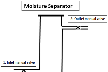
Installation orientation is an often overlooked, but critical factor in the performance of the system. Correct placement of the desuperheater can have a greater impact on the operation than the style of the unit itself. For most units, the optimum orientation is in a vertical pipeline with the flow direction up.
This is contrary to most installations seen in industry today. Other orientation factors include pipe fittings, elbows, and any other type of pipeline obstruction that exists downstream of the water injection point.
Spray water temperature can have a significant impact on desuperheater performance. Although it goes against logical convention, high–temperature water is better for cooling.
As the spray water temperature increases, flow and thermal characteristics improve and impact the following:
- Surface tension
- Drop size distribution
- Latent heat of vaporization
- Vaporization rate
Improvements in all these areas, as a result of increased spraywater temperature, improve the overall performance of the system.
The quantity of water to be injected will have a directly proportional effect on the time for vaporization. The heat transfer process is time dependent and, thus, the quantity of spraywater will affect the time for complete vaporization and thermal stability.
When designing a new desuperheater installation, another concern for proper system performance is the pipeline size. As the line size gets larger, more attention must be paid to the penetration velocity of the spray and the coverage in the flow stream.
Some single-point, injection type desuperheaters have insufficient nozzle energy to disperse throughout the entire cross sectional flow area of the pipeline. As a result, the spray pattern collapses and thermal stratification occurs, that is, a sub-cooled center core that is shrouded with superheated steam.
This condition is normally eliminated after the flow stream has undergone several piping directional changes, but this is not always possible within the limits of the control system or process. Proper placement of high-energy, multi-nozzle units in the larger pipelines normally prevents the formation of thermal stratification.
The maximum and minimum velocity of the steam has a direct relationship on the successful mixing of the water. The velocity directly affects the residence time available for the water to mix with the steam. When the maximum velocity is too high, there potentially is not enough time for the water to mix before it encounters a piping obstruction such as an elbow or tee. Ideal maximum velocity usually ranges from 150-250 feet per second (46–76 meters per second).
When the minimum velocity is too low, turbulence is reduced and then the water droplets tend to fall out of suspension in the steam. As a rule, the minimum steam velocity in which water can remain suspended is approximately 30 feet per second (9 meters per second).
For applications with lower velocities, proper mixing may be achieved with desuperheaters that offer a venturi or atomizing steam.
One of the most over-used and misunderstood concepts in the area of desuperheating is turndown. When applied to a final control element, such as a valve, turndown is a simple ratio of the maximum to the minimum controllable flow rate.
Turndown is sometimes used interchangeably with rangeability. However, the exact meaning differs considerably when it comes to actual performance comparisons.
A desuperheater is not a final control element, and as such, its performance is directly linked to its system environment. The actual system turndown is more a function of the system parameters rather than based on the equipment’s empirical flow variations.
Once this is understood, it is obvious that a good desuperheater cannot overcome the failings of a poor system. They must be evaluated on their own merits and weighted accordingly.
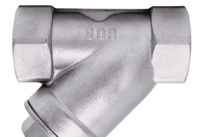
Due to improved nozzle design technology, pipe liners are rarely required. Depending on the particulate quality of the water source, in-line strainers may be required.
Desuperheater Design and Size
Some special calculations and recommendations provide the necessary information to select the proper desuperheater design and size.
This selection should be based on a variety of application considerations such as:
- Minimum to maximum load requirement rangeability
- Minimum steam velocity
- Straight pipe length and temperature sensor distance after the desuperheater
- Steam pipe line size and
- Pressure differential between water and steam
Read Next: Desuperheater Design


good informativ contents plz give me a pdf file for desuper heatet installation .
Nice article…keep it up.