Instrumentation Tools assists you a complete guide which mainly targets the aspirants of Electrical, Electronics and Instrumentation Streams to crack the interview.
Here’s a definitive list of Distributed Control System Interview Questions that will guarantee a sail-through to the next level as the guide been prepared in a strategic manner.
In case you have attended any competitive exams or interviews recently, or have additional questions beyond what we covered, we encourage you to post them in our Inst Forum to discuss about it further.
Proportional (P) Controller is used during the following conditions:
Integral (I) controller is used during:
Proportional and Integral action is employed when
PD action is employed when:
PID controller is used when system requires:
Presently this is best achieved by using a smart temperature transmitter with two sensors transmitting a signal proportional to the temperature difference.
This can be typically achieved by two ways:
By connecting o/p of one I/P converter to two positioners adjusted suitably for split range operation of control valves.
Taking two AO from DCS. Split range to be defined in DCS. Both I/P converters and positioners to be calibrated with input as 4to20 ma dc and 3to15 psi respectively.
Primarily depends upon the availability of reliable power supply source & application.
share answers through comments
This is typically performed in modern programmable instruments by means of measuring actual reference junction temperature using a temperature sensor mounted close to the ref. junction and compensating for the same using appropriate look-up table stored within the instrument’s memory.
Also Read : Certified Automation Professional (CAP) Questions
Three wire is a better alternative. Primary objective of 3-wire and 4-wire arrangements is to eliminate effects of lead resistance on temp. measurement.
Density is measured here by measuring the resonant frequency of a vibrating U-tube.
In most modern instruments the signal may be programmed to go to either maximum or minimum depending upon end user’s requirement.
Usually there is a blocking diode to protect the transmitter against supply reversal and almost zero current signal should be transmitted.
Fuse blowing sometimes. Power circuits are most likely to fail.
We can only measure sensor output (resistance / maillots ) accurately and look-up corresponding temperature in reference tables.
The accuracy depends upon quality / condition of the sensor. Degraded sensors may not give accurate readings and must be replaced.
To test a sensor, the sensor response may be tested using a high quality temperature calibrator and compared with reference tables.
Refer to instruction manual for the positioner / control valve. The cams are often marked with limited amount of information, which may help an experienced person.
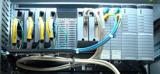
A field terminal assembly is a DCS component where field signals are terminated. In a DCS using analog transmitter signals but smart remotely configured transmitters field signals from barriers are first brought to a HART patch panel.
From here the analog signals are wired to the DCS field termination assembly or I/O card.
The digital signals are wired to the HART multiplexes who extract the digital information and provide two way communication path between smart instruments and a computer running suitable software.
A protocol defines a standard method for communications.
A fieldbus is a multidropping arrangement where multiple instruments communicate with special interface hardware using the same pair of wires and in most of the cases draw power from the same pair of wires.
Control System in which output quantity has no effect on the input quantity is called Open Loop Control System. Open Loop Control System has no facility to correct automatically the error generated in the output.
From output of the system no feedback is given back to the input for correction. In Open loop control system the output can be varied by varying the input.
But due the external disturbance system output may change. Any variation in the output from the desired once again attained by varying the inputs manually.
Advantages:
Disadvantages:
Control system in which the output has an effect on the input quantity in such a manner that the input quantity will adjust itself based on the output generated is called Closed loop Control System.
Open loop control system can be modified in to closed loop control system by providing a feedback. This feedback automatically corrects the changes in the output due to external disturbance.
Hence closed loop control system is called automatic control system.
Advantages:
Disadvantages:
The barrier if installed limits electrical energy flowing into hazardous area. If there is no barrier, typically a fuse in the power distribution system will blow.
– Share Your Answer though comments
A cold junction compensated instrument will typically indicate temperature of the location where the T/C wires are shorted.
Share Your Answer through comments
A minimum loop resistance is required so that modulated current signal produces a modulated voltage signal, which may be detected by the receiving equipment.
It is a transmitter part for allowing process connection to pipe/tube.
The design engineers / equipment manufacturers follow/publish certain guidelines w.r.t. different types of cables and the voltages/currents and types of signals carried by them.
You may use Ziegler-Nichol’s method ( open loop / closed loop ) or special tuning software tools.
Differential inputs provide better common mode rejection and signal-to-noise ratio.
When ground wiring is not done properly, grounding of various points is not effective and potential differences exist between them resulting in currents flowing between them.
This leads to measurement errors and is not desirable. It can be eliminated by proper ground wiring.
Control valves must be installed as per direction marking provided by the manufacturers or instruction manuals. Though people tend to generalize, this is often misleading.
ATEX/FM/CSA certifications generally refer to certification for suitability of instruments for use in hazardous area when installed in accordance with recommended guidelines.
Any certification, which is locally acceptable as per statutory requirements, may be used. We typically accept American/European/Indian certifications/approvals in India.
Some tachometers provide analog output with almost instantaneous response time.
They are highly suitable for speed control in some applications.
Inductive proximity switches are better suited for detection of conducting metal objects and are easily tested for proper operation.
Capacitive switches are typically used for detecting non-conductive materials
You can find out more about thermocouple accuracy and temperature ranges on this thermocouple color code table.
It is important to remember that both accuracy and range depend on such things as the thermocouple alloys, the temperature being measured, the construction of the sensor, the material of the sheath, the media being measured, the state of the media (liquid, solid, or gas) and the diameter of either the thermocouple wire (if it is exposed) or the sheath diameter (if the thermocouple wire is not exposed but is sheathed).
It depends on the instrumentation. If there is any chance that there may be a reference to ground (common in controllers with nonisolated inputs), then an ungrounded probe is required.
If the instrument is a handheld meter, then a grounded probe can almost always be used.
The magnitude of the thermoelectric voltage depends on the closed (sensing) end as well as the open (measuring) end of the particular thermocouple alloy leads. Temperature sensing instruments that use thermocouples take into account the temperature of the measuring end to determine the temperature at the sensing end.
Most millivoltmeters do not have this capability, nor do they have the ability to do non-linear scaling to convert a millivoltage measurement to a temperature value.
It is possible to use lookup tables to correct a particular millivoltage reading and calculate the temperature being sensed. However, the correction value needs to be continuously recalculated, as it is generally not constant over time.
Small changes in temperature at the measuring instrument and the sensing end will change the correction value.
You have to consider the characteristics and costs of the various sensors as well as the available instrumentation. In addition, Thermocouples generally can measure temperatures over wide temperature ranges, inexpensively, and are very rugged, but they are not as accurate or stable as RTD’s and thermistors.
RTD’s are stable and have a fairly wide temperature range, but are not as rugged and inexpensive as thermocouples. Since they require the use of electric current to make measurements, RTD’s are subject to inaccuracies from self-heating.
Thermistors tend to be more accurate than RTD’s or thermocouples, but they have a much more limited temperature range. They are also subject to selfheating. Infrared Sensors can be used to measure temperatures higher than any of the other devices and do so without direct contact with the surfaces being measured.
However, they are generally not as accurate and are sensitive to surface radiation efficiency (or more precisely, surface emissivity). Using fiber optic cables, they can measure surfaces that are not within a direct line of sight.
Thermocouples produce a voltage output that can be correlated to the temperature that the thermocouple is measuring. The documents in the table below provide the thermoelectric voltage and corresponding temperature for a given thermocouple type.
Most of the documents also provide the thermocouple temperature range, limits of error and environmental considerations.
Also Read: Questions on Standards & Field Instruments
If you liked this article, then please subscribe to our YouTube Channel for PLC and SCADA video tutorials.
You can also follow us on Facebook and Twitter to receive daily updates.
Read Next:
In this article, a simple example will teach you the conversion from Boolean algebra to…
In this article, you will learn the PLC cooking timer example for kitchen automation using…
Learn an example PLC program to control a pump based on level sensors using ladder…
In the PLC timer application for security camera recording, when motion is detected then camera…
In this example, we will learn batch mixing with PLC ladder logic program using timer…
This PLC example on manufacturing line assembly is an intermediate-level PLC program prepared for the…

View Comments
Where we have to know the dcs
good answers ... i want learn DCS ..where coaching is avilable .
Yokagawa technical school at Bangalore, electronic city
i want to download q and answer in the form of pdf. how to download please help.
for pdf download go to print and change destination and save as pdf
Me also
simply
good document. thanks